Trevor Gale's Amateur Radio News Page.
Tuesday 3rd October, 2009 Updated Latest!:
It seems now that I should separate out the Amateur Radio activities from the rest of the
Engineering side of this Web site, since I appear to be doing rather a lot on that at the moment.
The latest project (the others have taken something of a back set at the moment)
is what a close friend referred to as "my latest erection"
to be a little crude about it (it gets even worse - there are photos
following this to show the progress of this effort) and actually relates
to the erection of an antenna mast which is extendable by indoor electric control
to vary its height. Down at base level, i.e. not extended, it is only 6.5m above ground,
but I can extent it upwards to a total height of over 24 metres and with
antennas on top of that it comes to a good height for, especially, UHF and SHF
reception / transmission which also makes for a more far-reaching ATV coverage.
This is not as simple a job as the photos make it appear - firstly, a large
pit has to be dug into which reinforced concrete is poured: into this concrete
before any setting occurs (indeed, as it is being poured) 4 securing threads
are inserted each with its own 'anchor', which is an extra bind of steel strength in the
concrete for these threads of steel. There must be correctly-spaced to match
the holes in the thick steel plate that is the base of the "foot" of the antenna
mast - this foor alone weighs some 250 kilogrammes. Upon this foot is hinged,
at the top of the foot, the outside of 3 insertable triangular structures
that form the rest of the mast and which can be raised or lowered.
So firstly (and these will be updated as completion nears) some photos of the mast
before, ready for, during and (hopefully) finally erected.
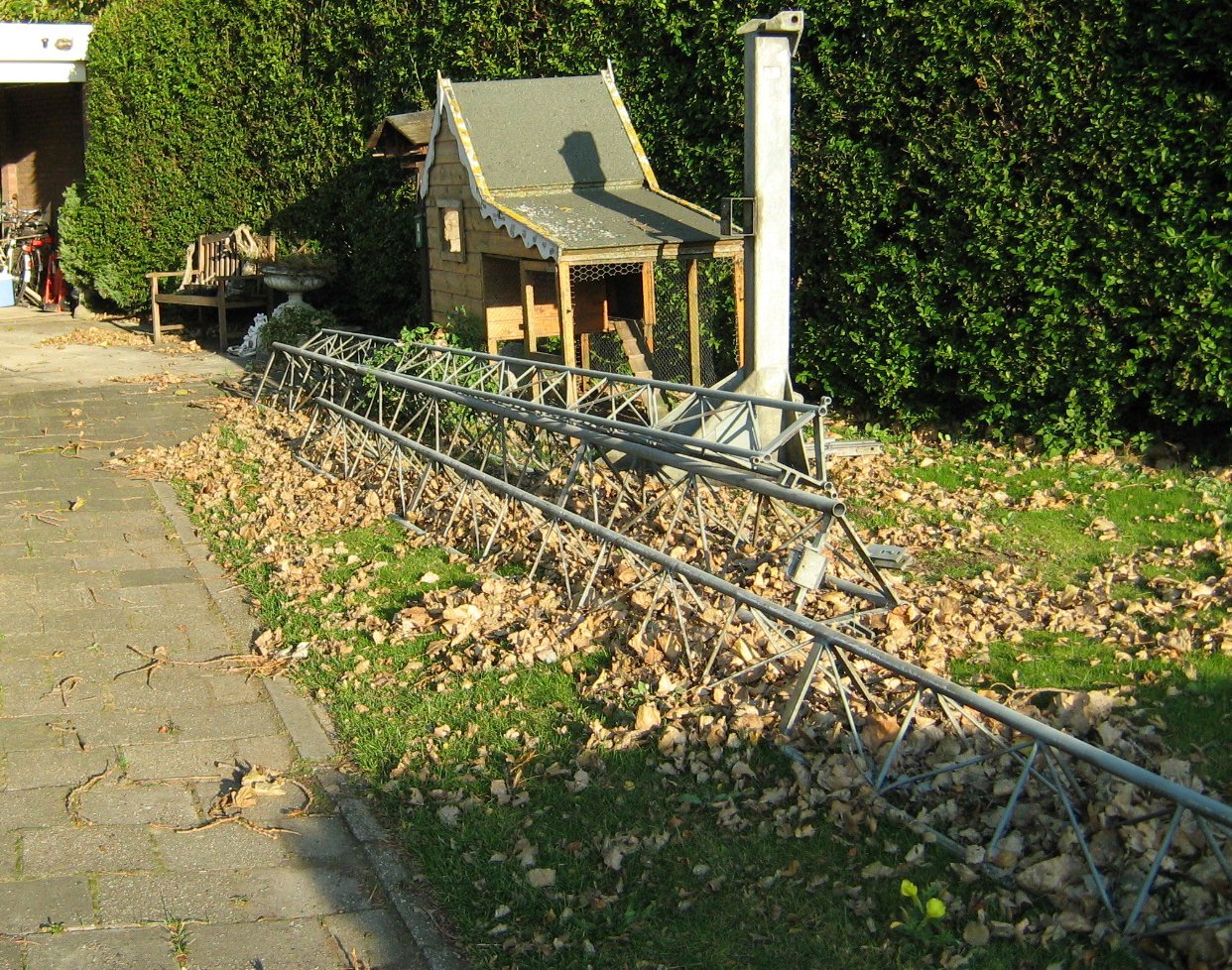
This is how things started here at the home location, the mast and its' mounting foot deposited in the side front garden grass area, to the right-hand side of the house as seen from the road:
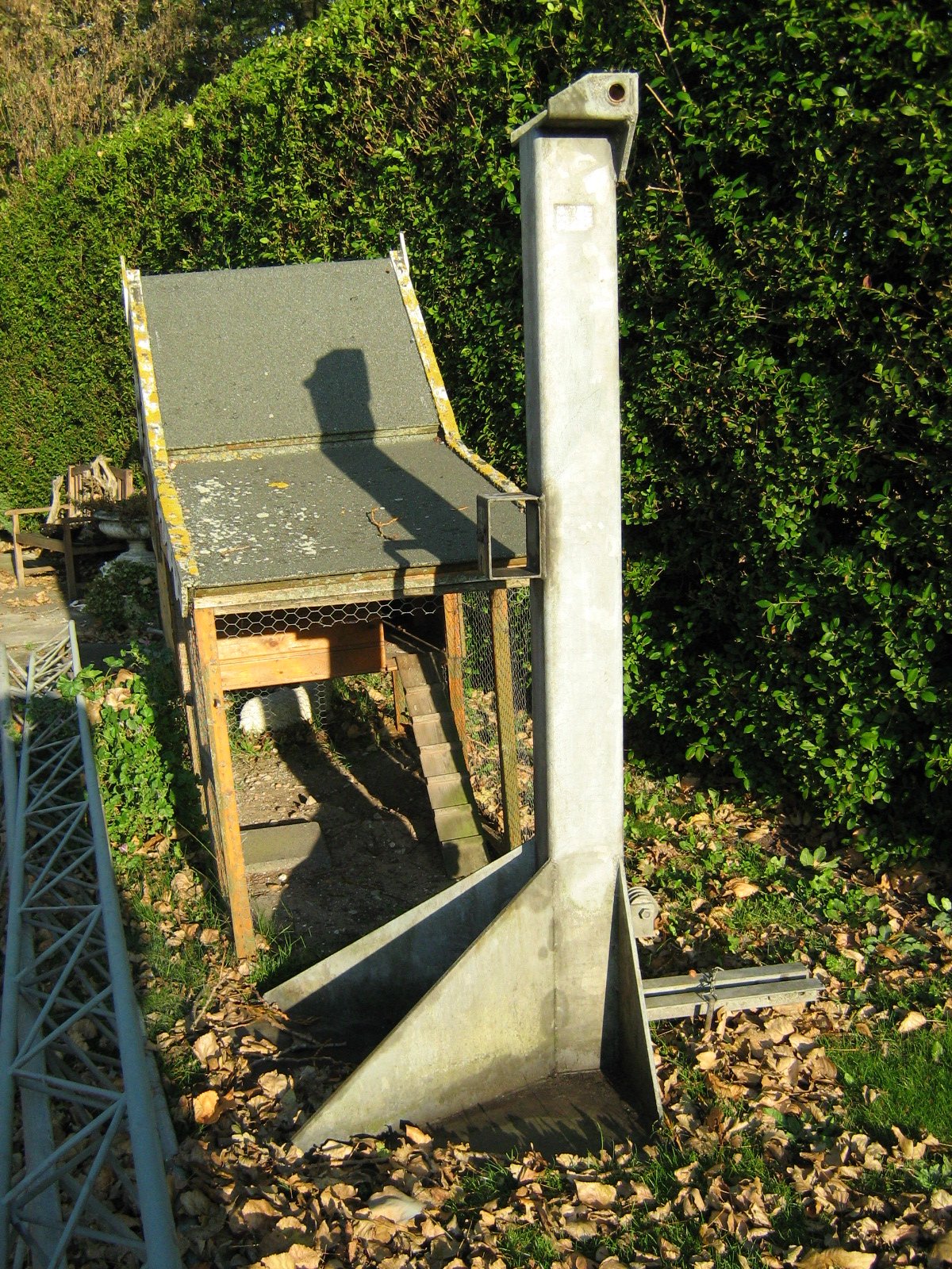
The 'foot' of the mast, which cmants on a hinge at the top of the foot when its inserted, can be seen closer in:
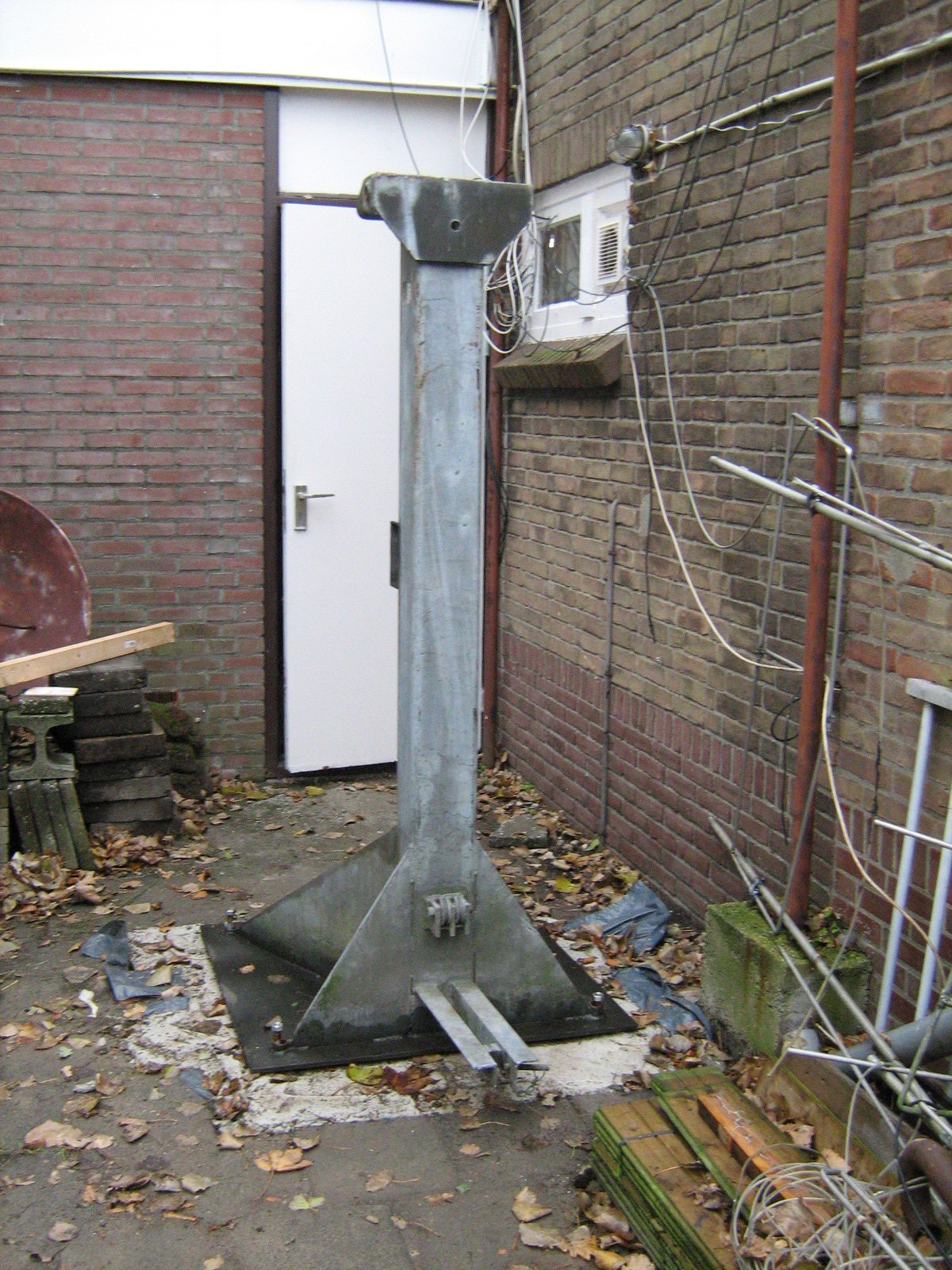
There aren't any photos of digging the 'pit' and of pouring the concrete, after all if you wmant to see that sort of thing just visit the nearest building site where they're putting up a shed or something! Suffice to say, that 3 weeks time was taken after the cement was poured for it to get hard, not just the surface but through the inside as well, naturally. So three weeks later, I had the 'foot' moved and placed over the protruding studding which matched the holes in the baseplate of the foot, into the correct place at the rear:
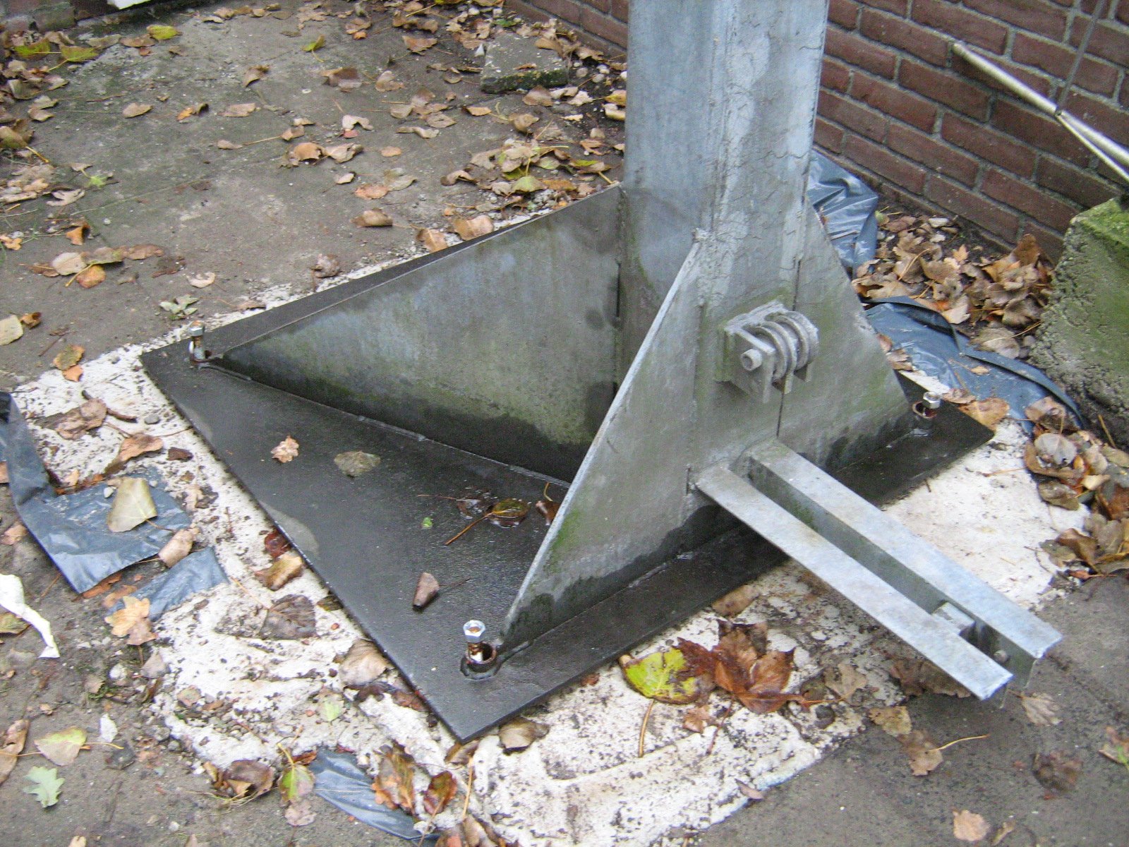
You can see the base of that foot and the threads through the holes but without and of the levelling collars yet installed:
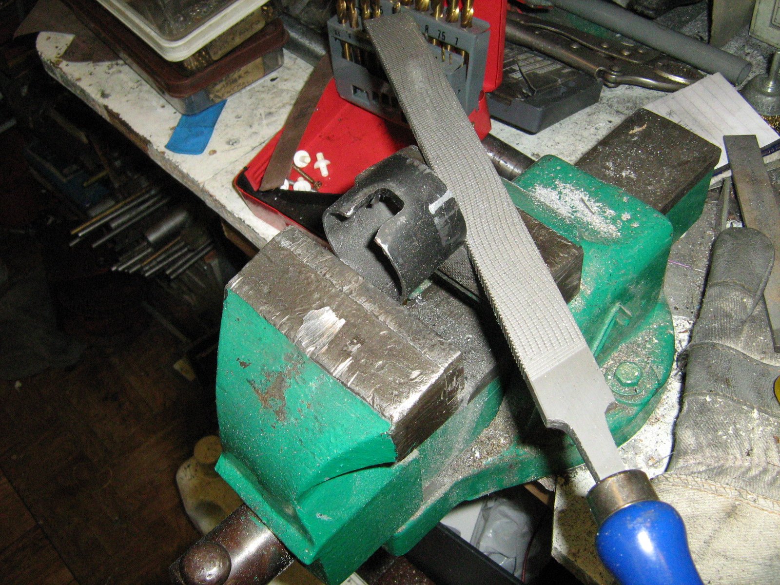
Next was some workshop metalwork, fashioning the mounting collars which slip over the threads to even the forces exerted by the nuts (and washers underneath) upon the base plate when tight. These were made by sawing (using a power hacksaw) the iron tubing and then cutting and filing the slots for the foot flanges as well as forming the level surfaces:
Next, the canting handle was to be fashioned, this was made out of brass with a thread cut:
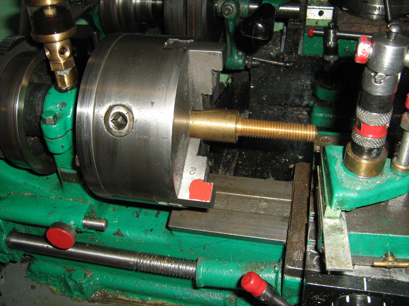
and an interior bore:
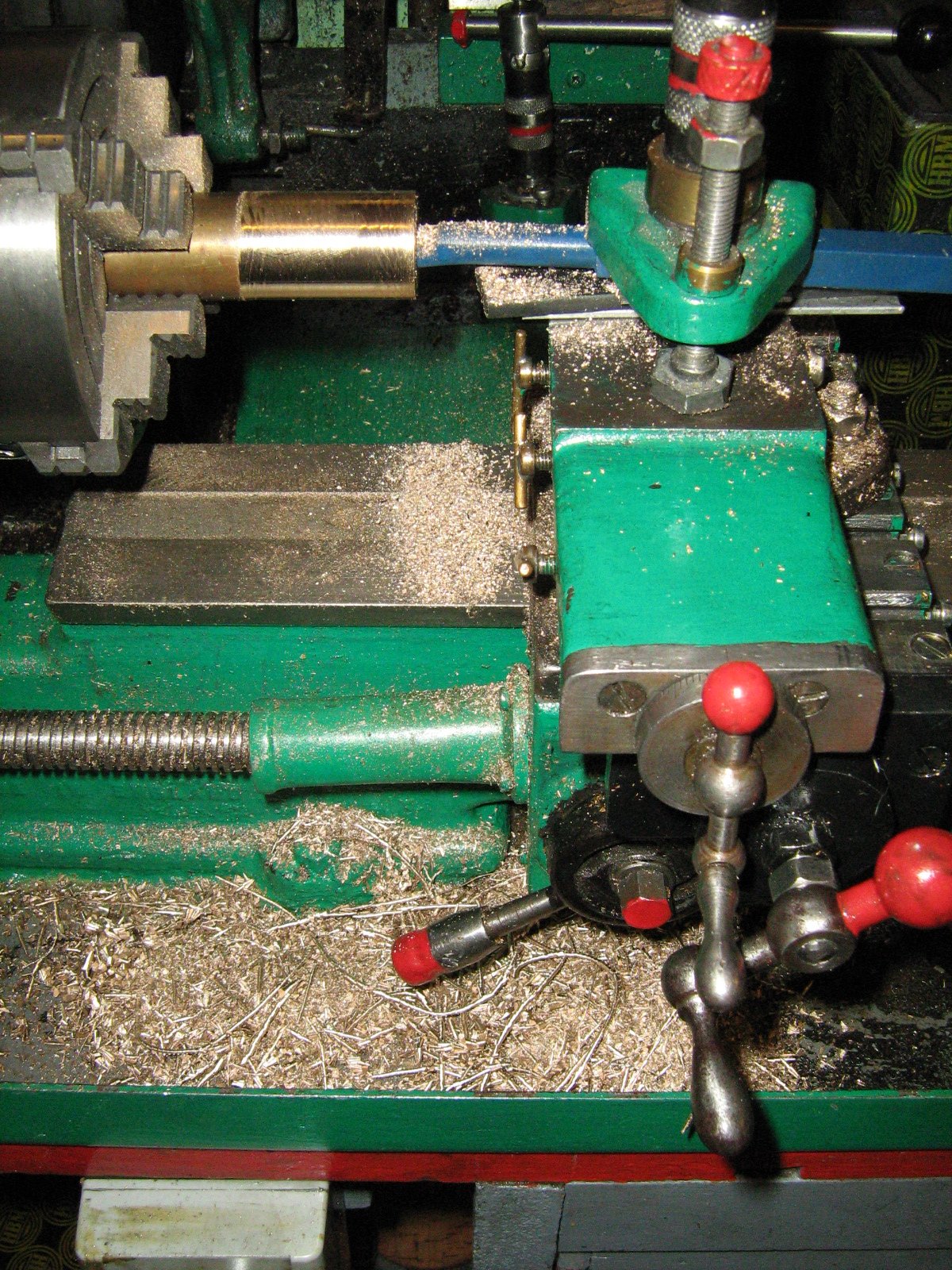
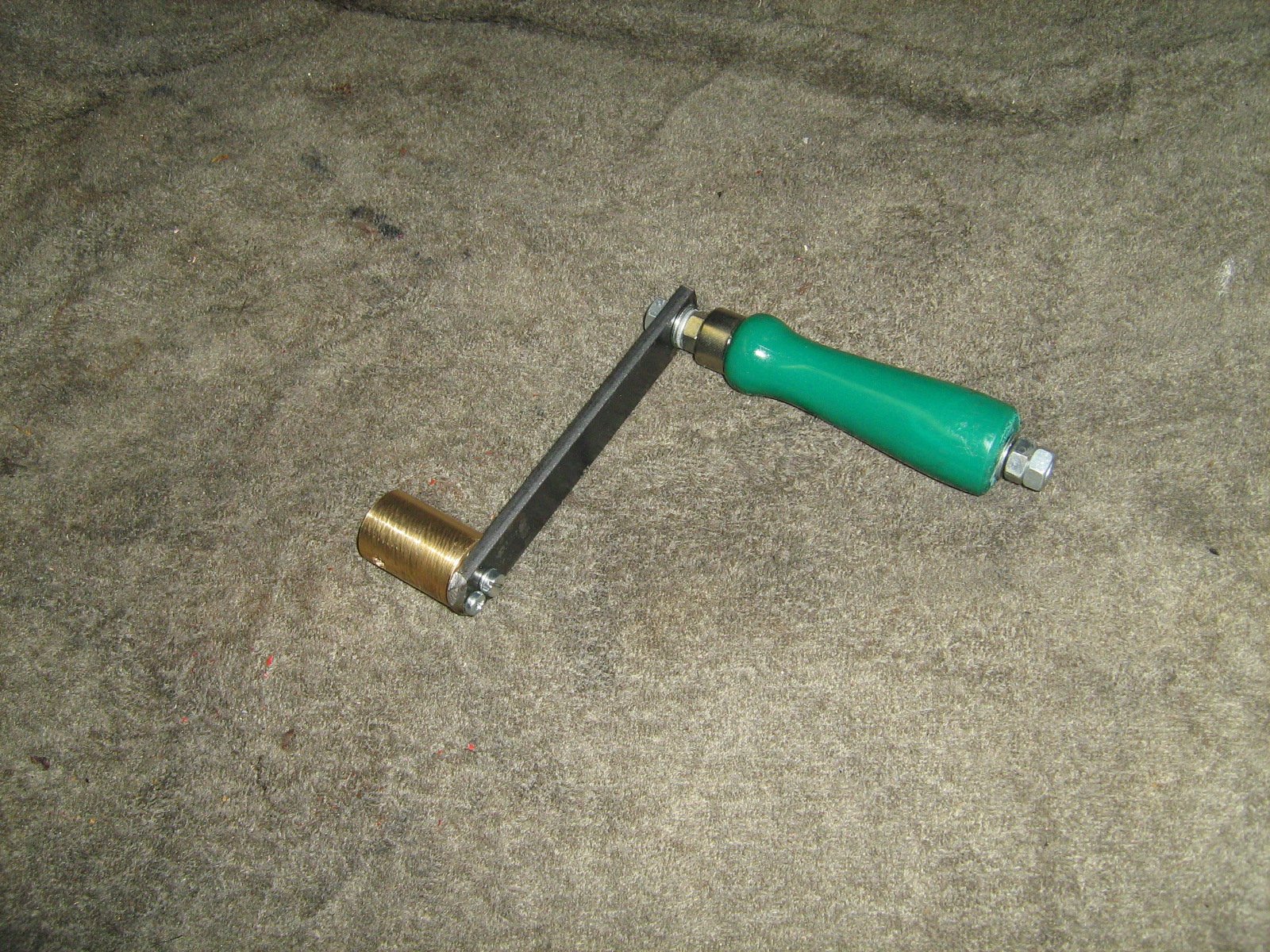
upon which was set a handle angle by drilling and tapping a short steel flat bar. A rough idea of the result prior to fine-filing and finishing is:
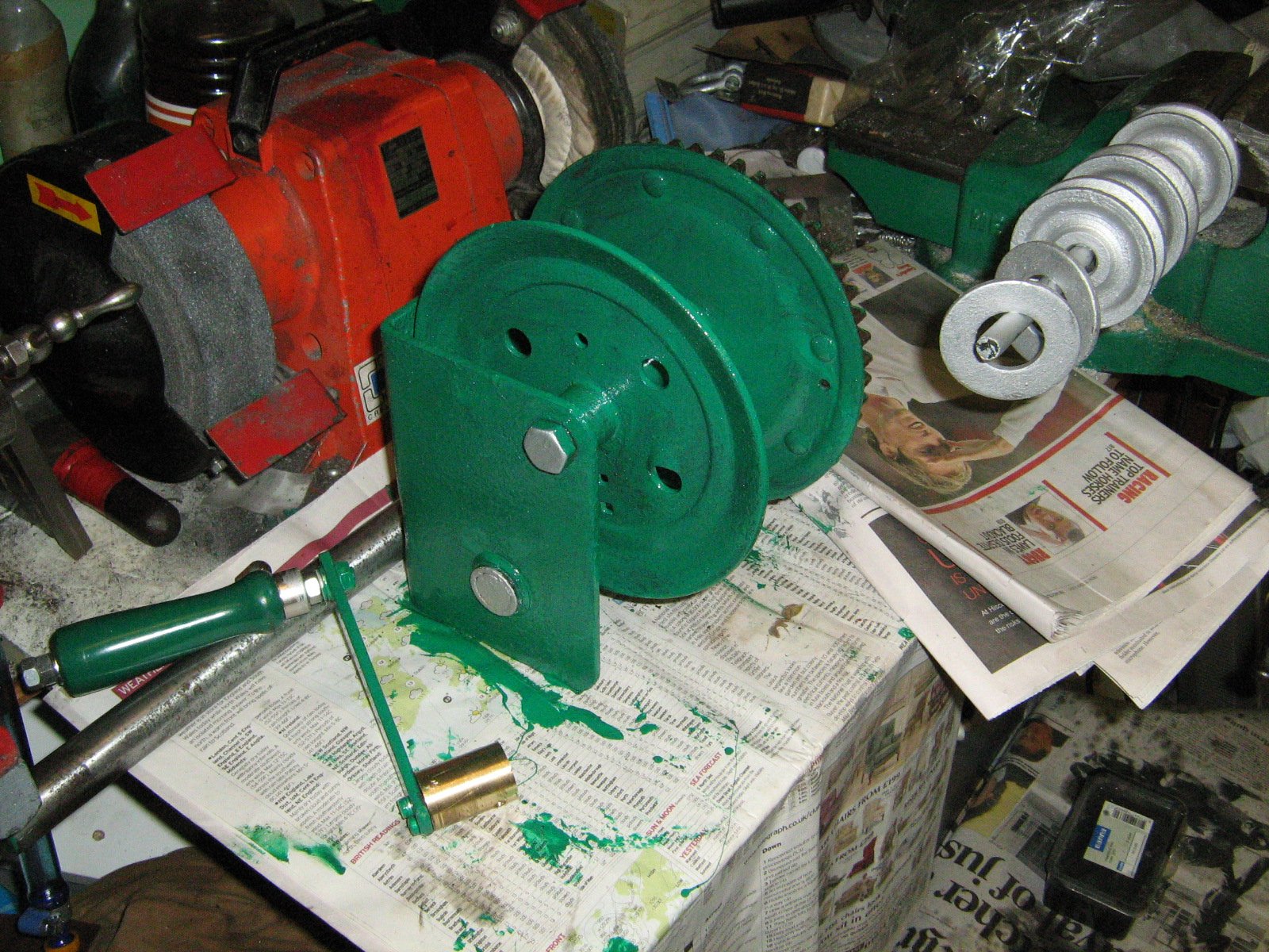
Next, the set of pulleys for elevating the mast using new steel ropes, as well as the washers which mount over the outside section hinge on top of the foot were prepared and protected:
A few days later I had the fellow from an antenna construction business and the two of us started moving the 3 sections over the garage roof, the outside section being immediately hinged and the hinge pin (1-inch diameter solid steel) inserted all the way through and then fixed by bolts and nuts at each end. The second section is then inserted:
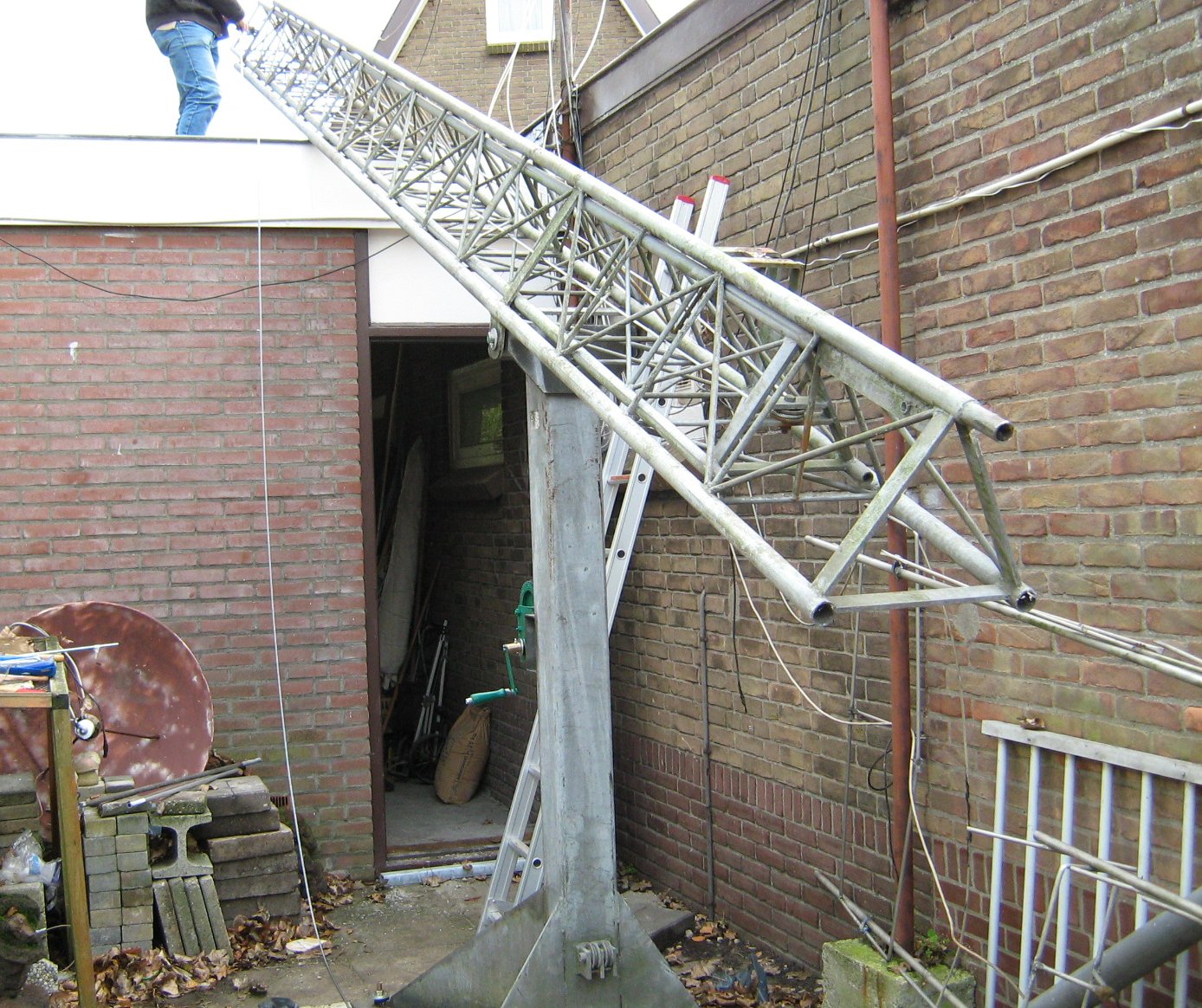
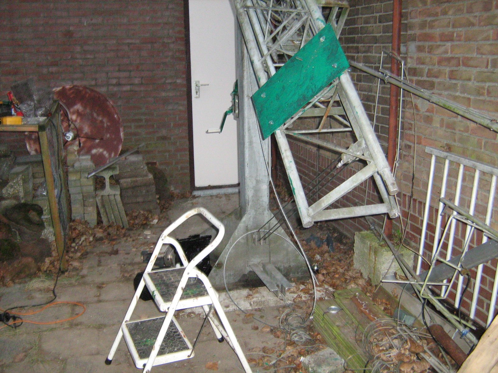
followed by the third (inside) section, the whole assembly is at this stage cmanted over for access just above the garage rooftop:
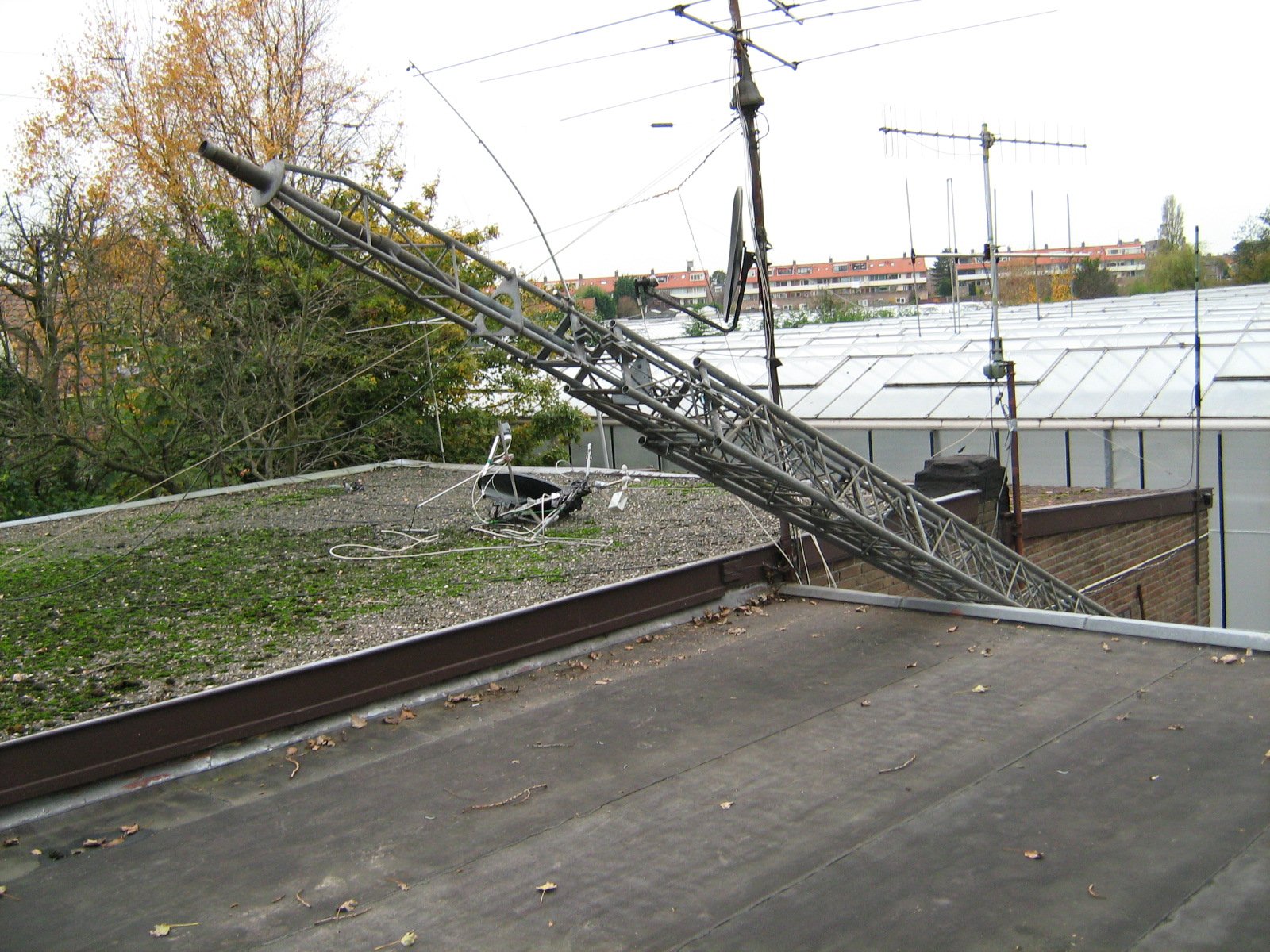
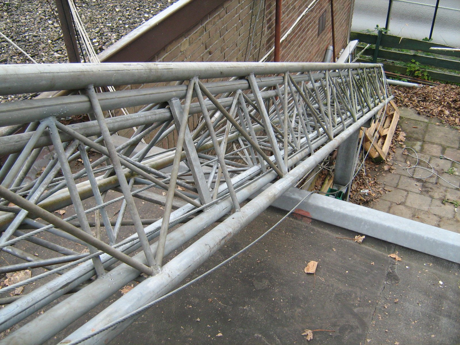
To see things "from the other end" as it were, this is how the (still retracted) sections look towards the ground:
Now the next job was to facilitate the elevation motor fastening to the outside of the outside section near its bottom; first a 10mm iron plate was used, drilled together to match the drilling in the legs at their lowest. Thinner plate would actually buckle here in operation, as the hasp on this motor winds the whole forces of the erection of the mast via a reduction pulley system up and down the mast. This plate was fixed, protected and then left to dry as it was getting late in this second days' work anyway:
The wiring of the switchgear for its first test was next on the agenda for the next day, together with various fixing and routing of supporting and pulling cables, so it was a bit of a mess with bits of cable around and so on:
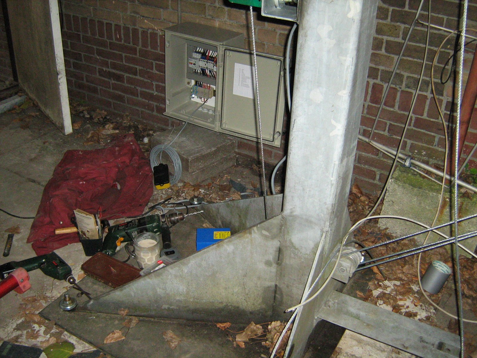
That done, the elevation motor was affixed to the pre-drilled plate (it is a continuous-rating 1.6 horse-power motor with a higher starting torque) but here it is (that black monster, weighs a ton) fixed ready for wiring and use:
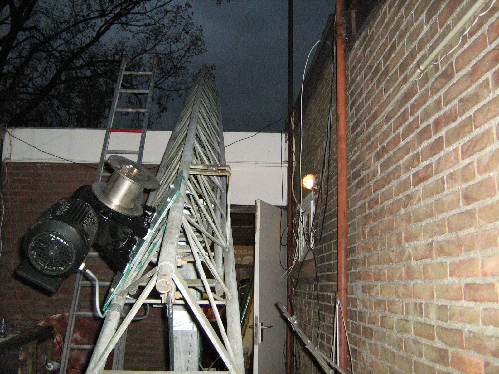
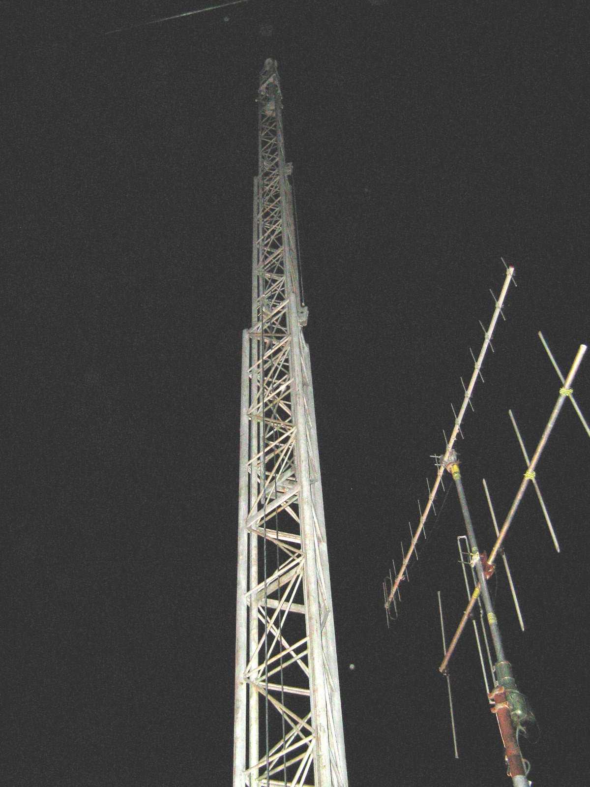
Now, already starting to get dark towards the end of the third day, the first tentative elevation test after de-canting to the vertical was done:
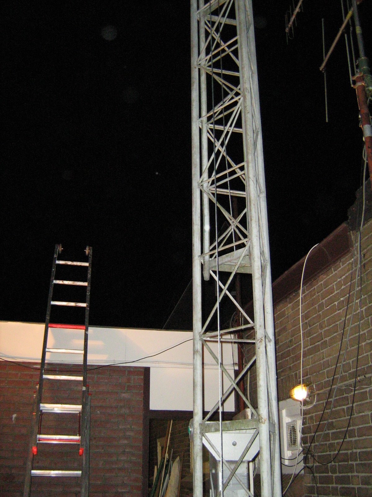
SHE'S UP!!! This is the first nearly-full erection in elevation of the three mast sections (they go up together, not successively) and at least proved all the hardest work was done okay.
Some smaller details
follow but they will be completed on following days and then all the antennas
together with the antenna rotator will be fixed. However that was definitely
the end of this days' work as it was already very dark and I had to work with
two lamps already providing 1KW of light.
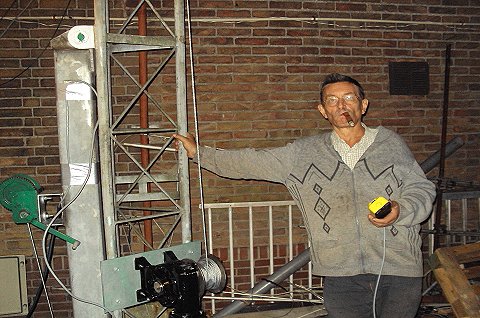
Clearly, this was a cause for a little self-indulgence was called for and so
I cut and lit a fine Churchill cigar gift to enjoy whilst I looked at the achievements
so far made!
More of the last parts of the commissioning of this follows - because even though I may celebrate the achievement so far, the antennas and so on have also to be mounted, aligned and tested... a process that started in the dark (!):
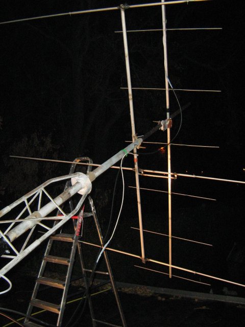
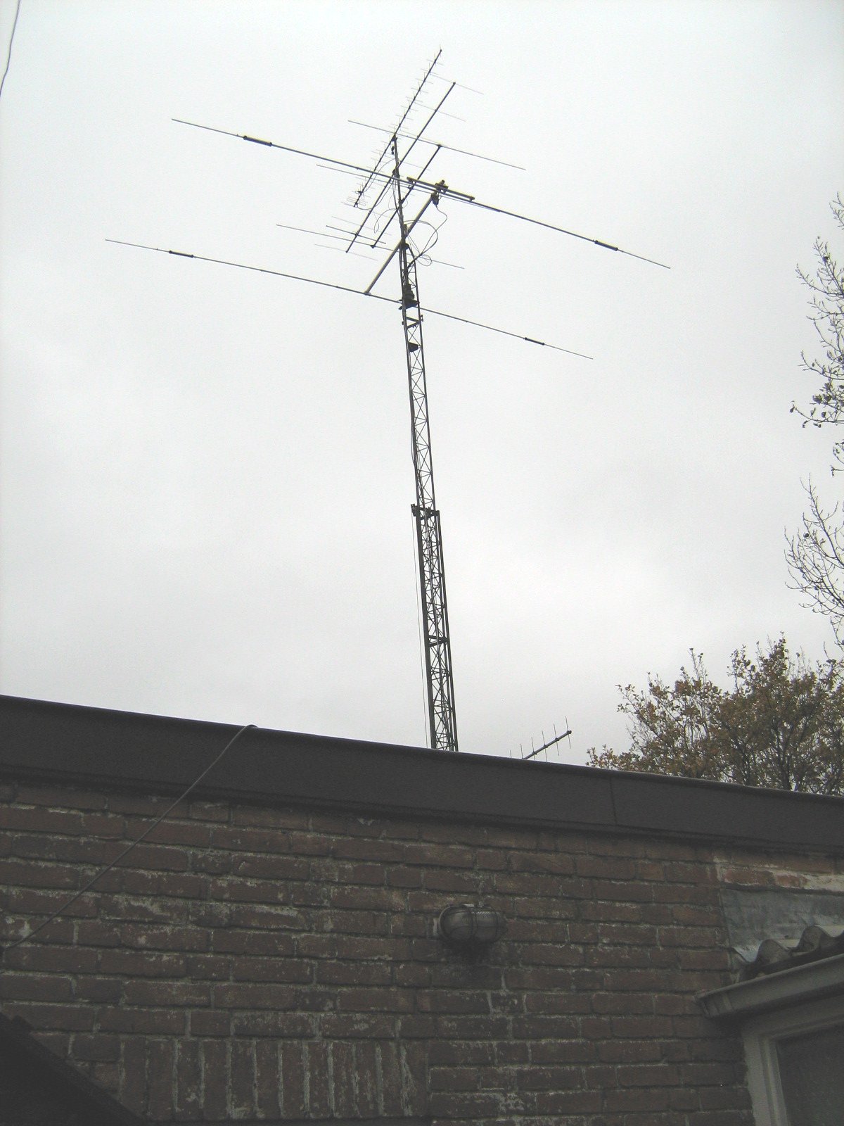
So, the following days' work went on from the first antennas affixed, the next 2 pictures show the mounting of the next 2 antennas on a grey blustery morning which was sometimes wet, quite cold and with a lot of wind:
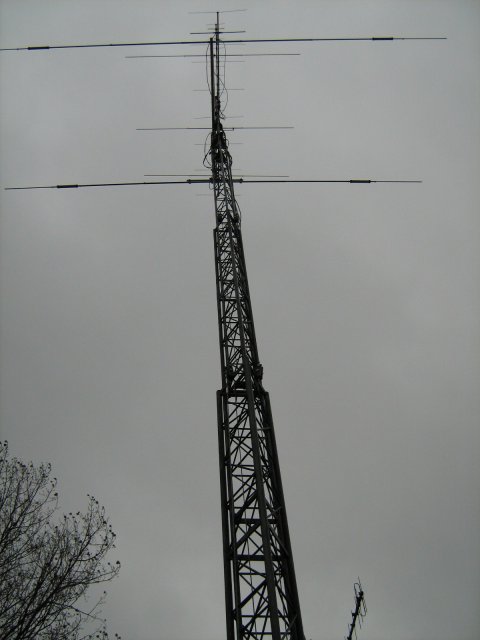
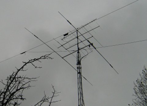
Following that work, a partial erection was achieved with some antennas on the mast for the first of a series of checks and tests:
More erection was accomplished and the antenna performance was very reasonable indeed:
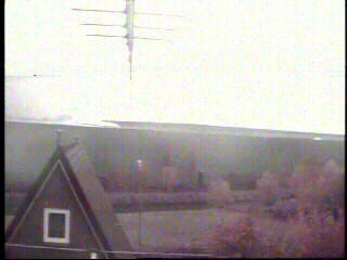
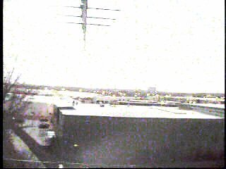
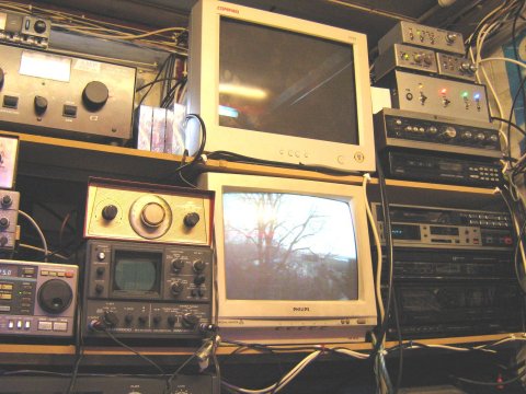
This also proved that the mast-mounted camera worked in differing lighting conditiond and although primarily intended as a CCTV (outdoor) device the resolution was sufficient for the job. The first shot is a still that shows the placement of the camera position on a partially erected mast as above our house (the attic window can be seen as can a view above our roof):
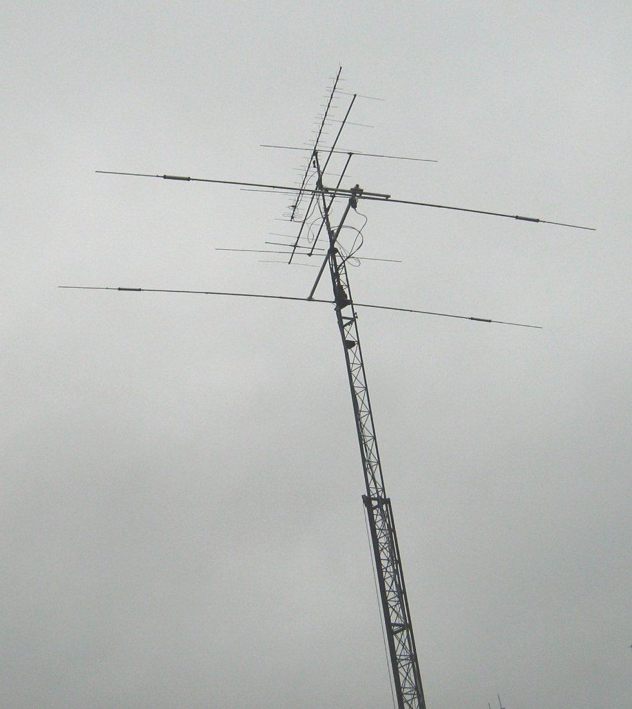
After further erection the terrain view can show that the antennas can make possible communication (especially at VHF / UHF / SHF) well over the top of adjacent items / buildings which would otherwise prove to be obstacles:
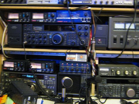
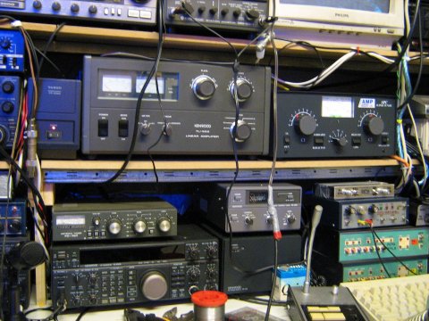
The checking and testing after connectors, cables, & etc., were installed was made using the new radio station layout (something of a mess due to all of the new cable routing and so on - a couple of these antenna cables are over half an inch in diameter); here are 3 of the station being used for the tests:
This evening, together with Jos / PA3ACJ, we performed an ATV exchange test which proved that even when not fully erect, new and far better signal paths exist as a result of the implementation of the new antenna mast.
Anyway that's the basic Radio and ATV news from here for now, so best 73's and 88's as appropriate - Trevor, G8GFH / PA2TG.
Thank you for reading, any images (c) F.C. Trevor Gale.
 You can E-mail the
author of these pages (Trevor Gale) by using
this link, or by sending mail to tgale@trevang.com on the Dutch Internet
service provider XS4ALL.
You can E-mail the
author of these pages (Trevor Gale) by using
this link, or by sending mail to tgale@trevang.com on the Dutch Internet
service provider XS4ALL. 