PA2TG (Trevor Gale)'s Radio Web Page.
 ...
...
UPDATED AGAIN FINALLY! - 23rd June 2014 (not so late this time... !).
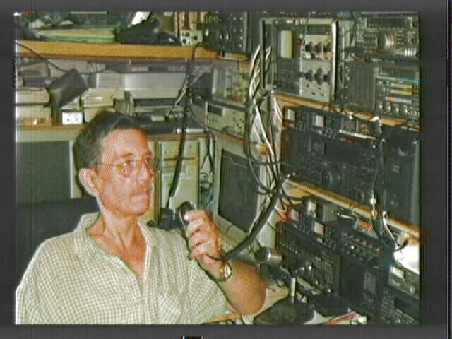
ATV !!! My ATV station is
fully on-air, with work going on for new bands as well.
With this update, old and ambiguous film content has
been cleaned up and old video removed.
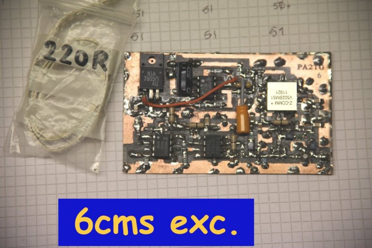
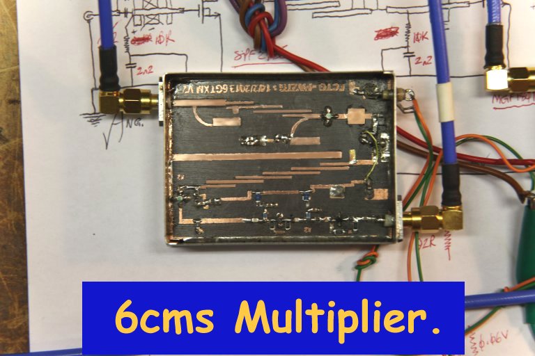
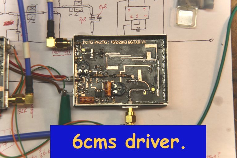
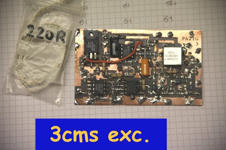
Well, I had already (a couple months ago) decided that instead of building "yet another box" for the
next ATV band (6 cms) that it would be better to get a bit cleaner in orgasining the whole ATV setup
instead of having things in so many places - so I've commenced the design and building of a full
dedicated-computer-controlled 6-band ATV main rig. One more board is complete as of this day, and
the next work is probably centred around the case / housing for the rig and the 5.6GHz antenna.
The design of it all is 99% complete, and I am
well on the way in the building process; it is a rig for 70cms, 23cms, 13cms, 6cms, 3cms and 1.2cms
(for 6cms, 3cms and 1.2cms the final multipliers and power amplifiers plus the preamps and downconverters
are located in mast-head units).
There are a few photos of the progress in the workshop for this rig below, and it is to be noted
that since the overall concept allows it there have been quite a few 'extras' and features that
I have brought into it which means that the overall project is more than twice (!) as much work
as I had originally thought it to be - but hopefully it will be well worth all the extra efforts
and perspiration that's involved.
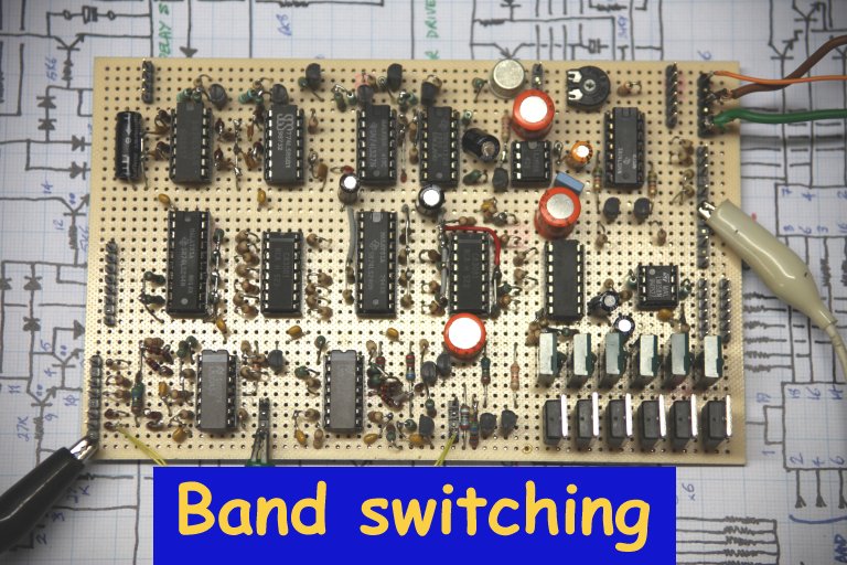
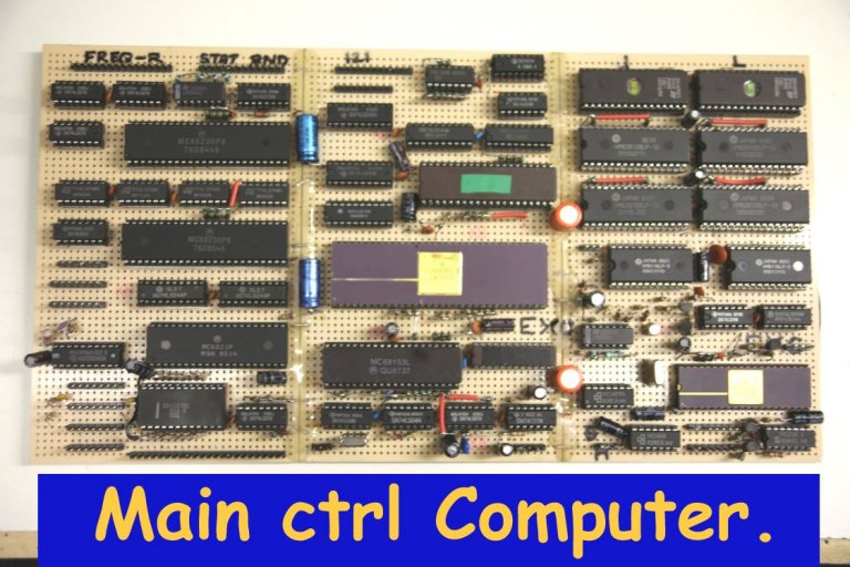
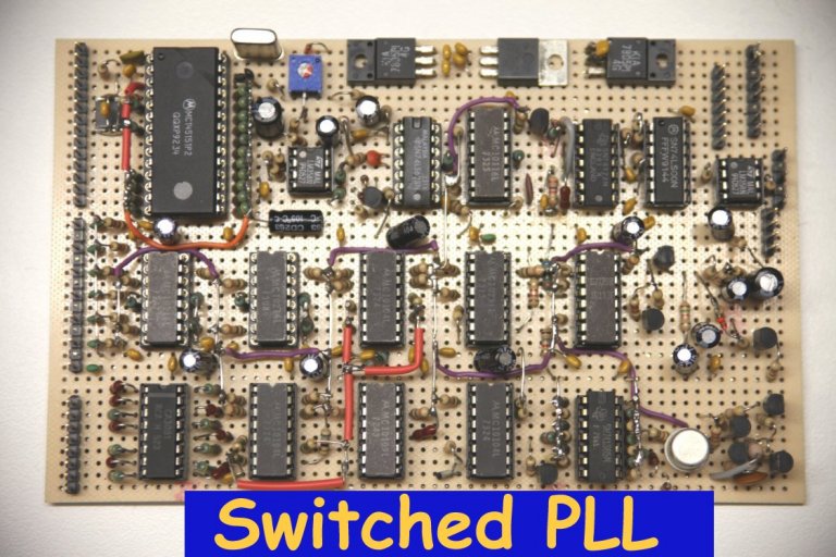
Basically the rig comprises a central dedicated computer system (around a 680x0-series CPU) which
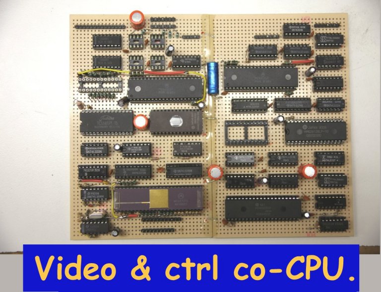
handles most operability and the user interface and control, a co-processor CPU unit which is
dedicated to intensive video generation and control, a switched dual-PLL which works for all the
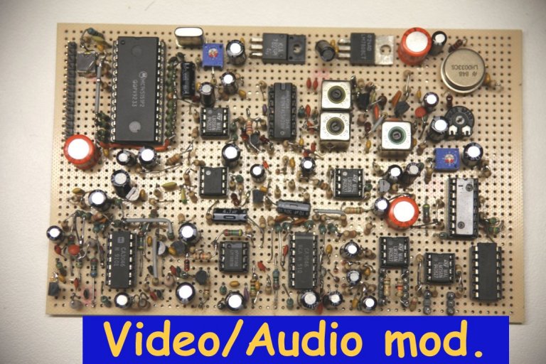
bands, a video and audio control / interface unit with an on-board sound-subcarrier PLL section,
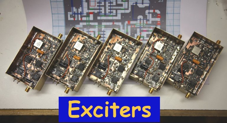
exciters for each of the bands which take the PLL output for frequency control and take the
control / interface outputs for modulation, a video sources selection board, and a power control
unit with an incorporated sequencer for TX/RX switching and timing. Obviously there is a
comprehensive control panel and display interface together with such features as masthead
telemetry (as I first implemented in the existing 3cms rig), multiple band and setup memories
(including items such as modulation width, subcarrier frequency and the like), R.F. power
monitoring & display, power-amplifier and temperature protection.
The overall unit housing has yet to be built but the dimensioning and layout is basically already drawn up and the display and metering I've decided upon and am planning into the panel. The whole thing can be operated from the front panel but is also comprehensively operable through the use of a video window or an external serial link to (e.g.) some desktop or laptop P.C. or even a tablet computer over a network. Just a few photos of some boards or units are shown below for an idea of what is going into this unit:-
Earlier developments:
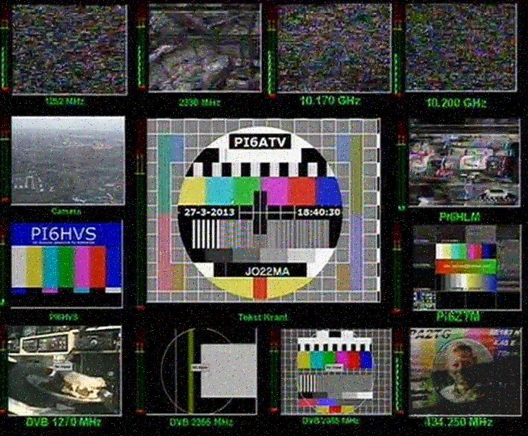
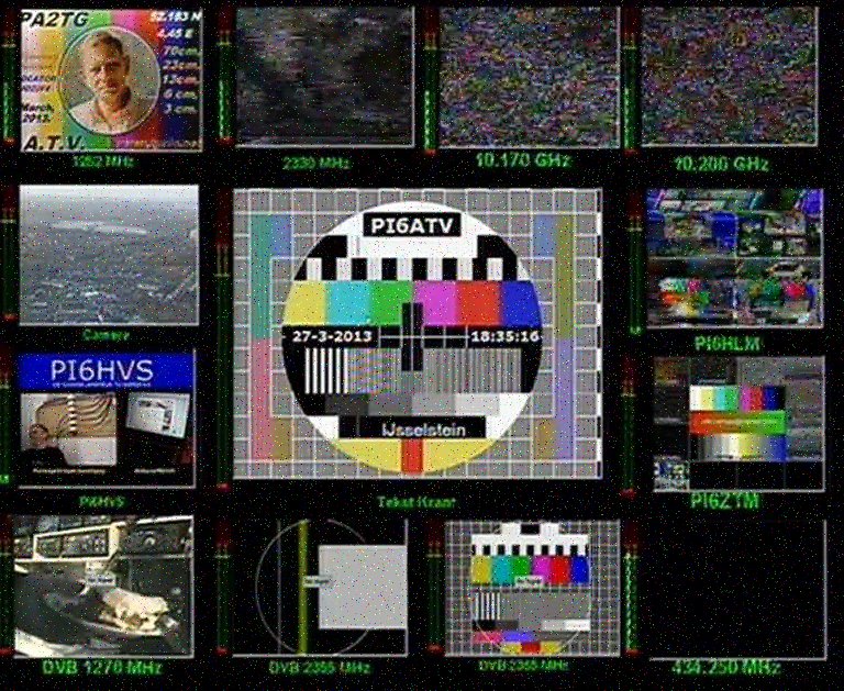
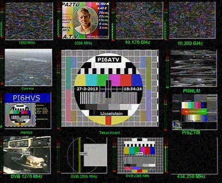
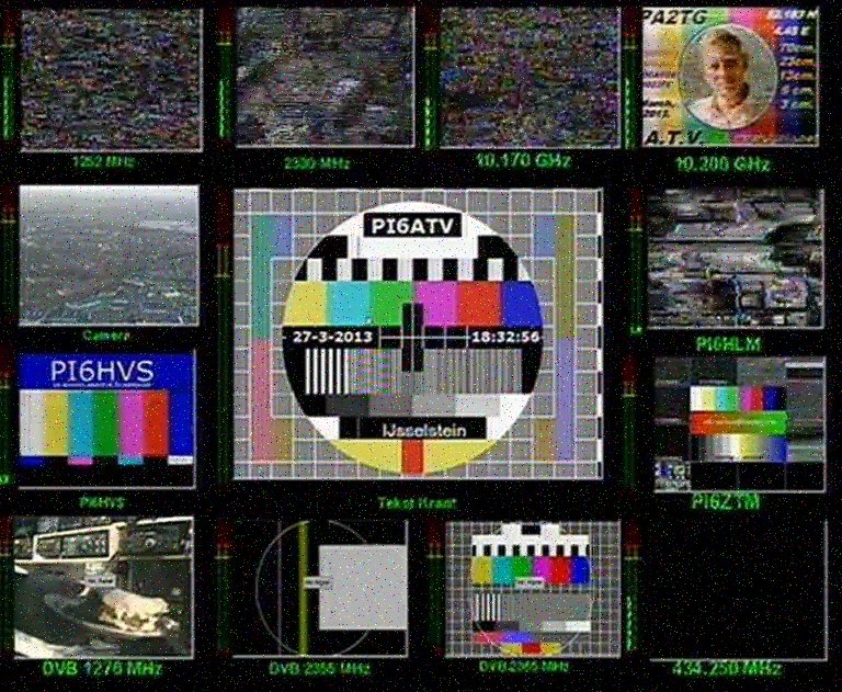
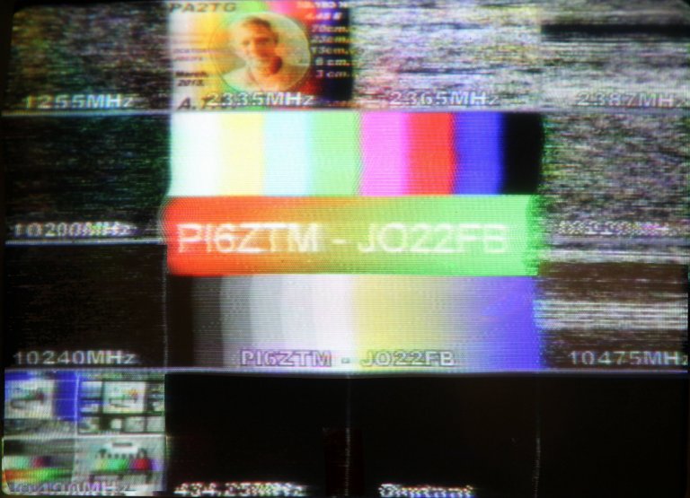
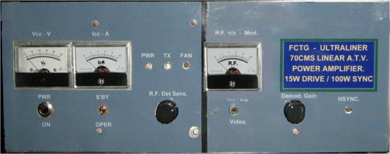
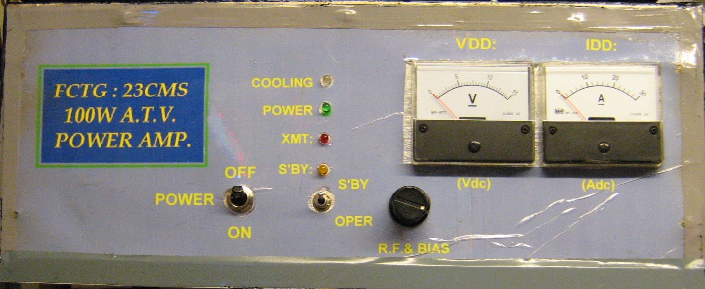
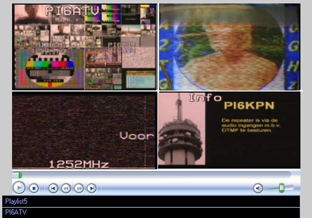
The latest work here at PA2TG includes the upgrade revision of the 23cms ATV final amplifier, which now delivers the 150W and has proved to work well into several of the repeaters receivable here. Using just the "monitor" 10GHz / 3cms facility it's been possible to receive and capture some of the received signals from, notably, PI6ZTM in Zoetermeer (10.150GHz), PI6HLM in Haarlem (10.250GHz), a well as PI6ATV in Ijsseltein (10.475GHz): at the time of this update it seems that the repeater PI6KPN in Den Haag (10.490GHz) is temporarily out of service. Some captures of my retransmissions to these repeaters are shown below:-
PI6ATV with 70cm:-
PI6ATV with 23cm:-
PI6ATV with 13cm:-
PI6ATV with 3cms:-
PI6HLM with 23cm:-
PI6ZTM with 13cm:-
The signals when using my "main" 10GHz long gain-horn and LNB are appreciably better but for this test I dedicated the
main horn set-up to the occaional 10GHz transmit tests. I receive a stronger 10GHz signal from PI6ATV then others using
the monitor horn.
For the 'next' band, the 6cms antenna will be a waveguide-fed Yagi, I really have very limited space in my mast
installation as it is now made, with the many antennas involved.
I also have to take care of wind considerations.
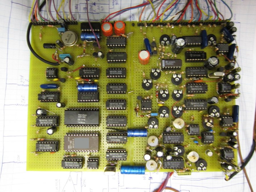
Other news from my workshop: the finalized version (version 4) of my video processor
has now been completed. It is far more
stable and at the same time flexible (if you know what you're doing and choose to use
one or more of the 'manual' controls rather than the in-built automatic ones). Here's an
idea of the basic board layout:-
All that remains to do now is the audio side of things, including auto-A/V reduction when the microphone
is used, audio vox, and tone equalization plus adaptive noise reduction. All of this latter
enables the best to be got from the audio as well as the video when, for example, re-sending
received ATV from another band, or replaying received ATV from another station that was
recorded previously.
NOTE!!! A NEW A.T.V. INTRODUCTION / TEST VIDEO is now available, and since there are
so many different video decoding and playing software options available for
one's computer nowadays, I have elected to make it available via the YouTube
resource facility which is far more universal and more widely acceptable.
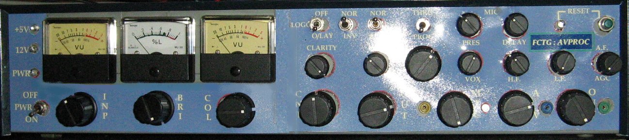
The "starting element" unit for the ATV side of things is an audio/video processor
of my design which allows the changing of picture characteristics, establishing
of the true black level and true blanking level, the inclusion of a callsign logo,
automatic cross-fade of microphone / background-or-selected audio, voice
depth control, and audio/video source selection. It also takes care of the
sequencing of the transmit/receive switching process, generating drive
signals that ensure switching is established before transmit carrier is
switched on and so forth. This has just undergone a series of updates, one of
which addresses pictre quality aspects and hue control.
A 70cm ATV R.F. filter precedes the
driver board, and the losses in this filter are made up by using an MAV-11
MMIC amplifier, which is well-cooled (presettable from the front panel).
The last unit in the 70cms transmit chain is the final power unit delivering
100W sync at 70cms, this is based around the use of a 100-W board adapted
from the telephony world, using an LD FET as the power device. Temperature
sensing is incorporated such that a dual-fan venting is variably switched
into use automatically - ONE CANNOT OVER-STRESS the need for adequate heat-sinking and
ventilation / cooling especially in the case of truly linear power stages
which of necessity operate at an effective efficiency of around 28% at these
frequencies.
An on-board demodulator was added to allow direct off-air transmit monitoring.
which incorporates auto-muting,
missing-sync regeneration based around two phase-locked loops, and a small
amount of analog signal optimisation electronics: use is made internally
of standard I.C.'s but with different-to-standard support circuitry, and
the receiver delivers two outputs, i.e. audio and video, for application
to an external monitor.
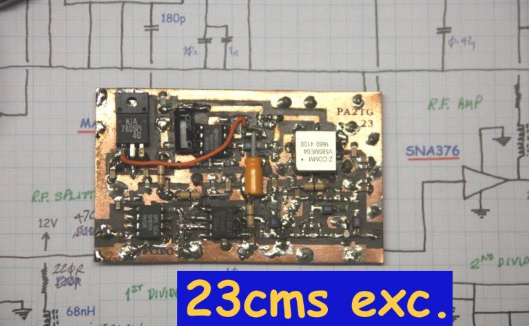
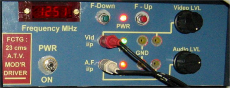
For 23cms (typically 1.252 GHz) the exciter stage is based around the widely
available VCO-based and I2C-controlled module which delivers some 4mW after
my filtering which
is amplified to a more acceptable level by the use of two MMIC stages, based
on the MAR-8 followed by the MAV-11 which provides the F.M. ATV exciter output
(+/- 40mW) at 50-ohms.
This is well heat-sinked,
with venting presettable from the
front panel. This driver actually can provide some 20 - 23 watts of output, and
I have used it - bare, directly out to the antenna - with good results.
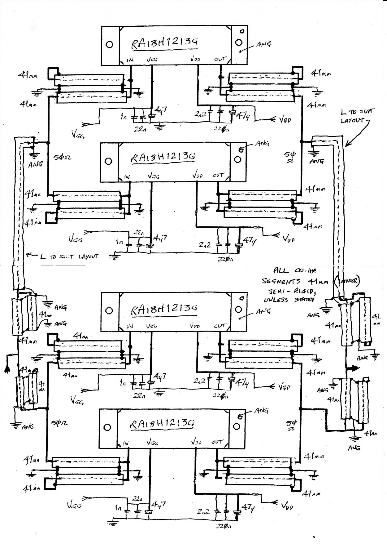
Following this is a 85W (nominal, more may be expected) power amplifier which
is driven by an attenuated driver unit signal (using a stripline coupler, the
exact coupling co-efficient being non-critical providing it does not result
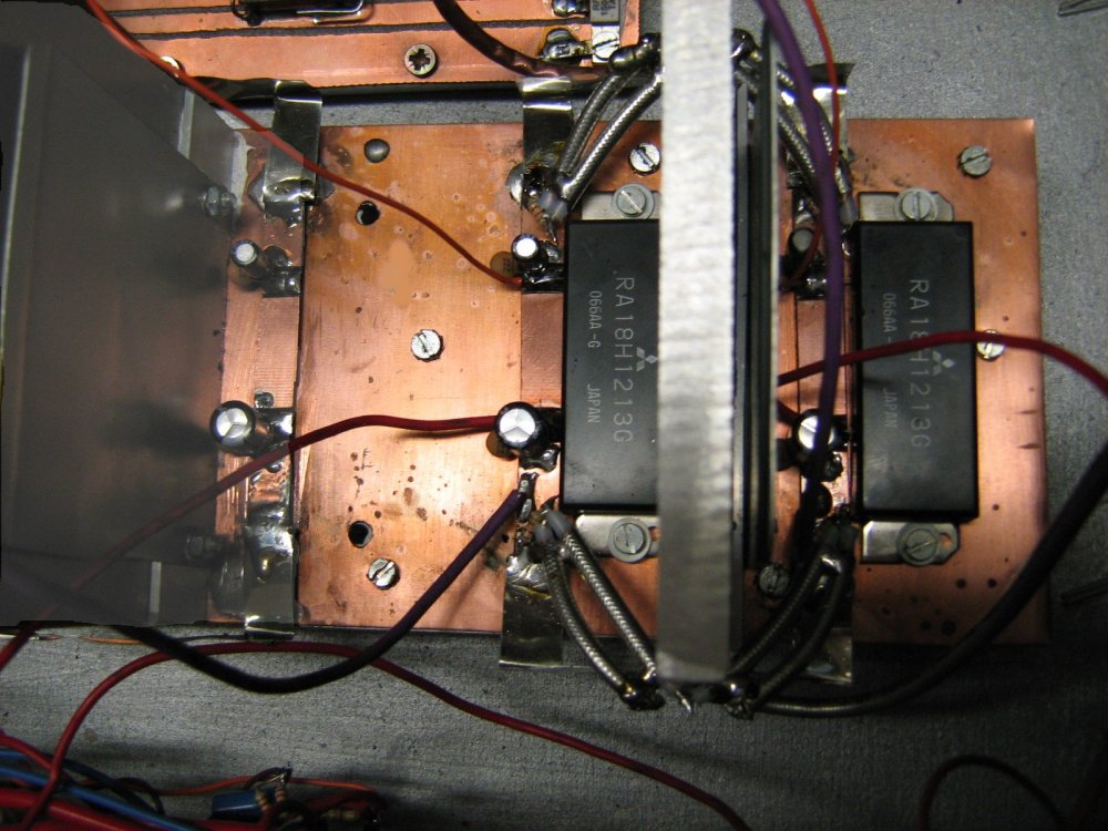
in the over-driving of the P.A. modules). This power amplifier (see below)
uses 4 of the Mitsubishi modules driven
and coupled utilising a combiner set manufactured using semi-rigid quarter-wave
matching line lengths to achieve a final power stage delivering some 102 - 110
watts. Here is a pair of the modules, heatsink mounted, under initial testing
in the workshop:-
The complete unit is actually on test in my workshop being built at this
time, and makes use of a switched-mode D.C. supply since the current
drawn by this final set of modules is of the order of 28 Amps. As much
work is involved in the design of the power supply and the cooling / ventilation
electronics control (two linearly-controlled vent fans) as is entailed in
the actual 1.250 GHz power stages, although the latter does require a little
effort on the mechanical side. Again, the proper cooling arrangements for
such devices cannot be over-estimated; they are very important and in this
power amplifier use is also made of a copper layer as a heat spreader above
the aluminium first heatsink pad. The final result will is to be seen:-
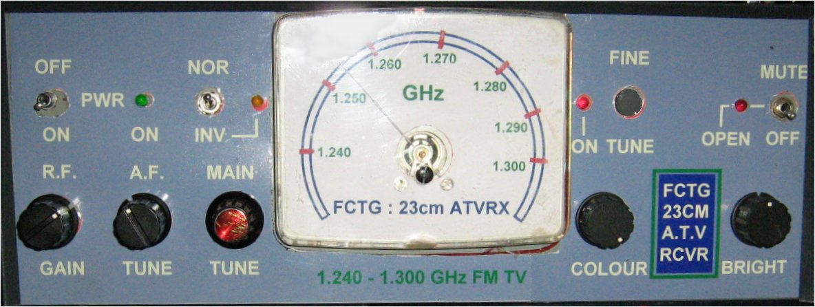
Whilst this is reasonably sensitive it is still supported by a preceding bipolar
R.F. amplifier (a first-stage FET pre-amp is designed and will precede this
unit when completed). The composite video output from this tuner is split
into 3 paths, i.e. the main video path, the sync/mute path which is used by the
auto muting and sync support circuitry, and the F.M. sound subcarrier path,
where I use a TA7130P quadrature demodulator tuned by a pair of vari-cap
diodes to receive 5.5 - 7.5 MHz sound. To avoid vision-on-sound and to
ensure good limiting characteristics I employ a broad H.F. amplifier with
a high-pass filter and dual-vari-cap tuning tracked to the 5.5 - 7.5 Mhz
demodulator tuning. Due to the wideband nature of the ATV use of this band
and the linear nature of the tuner frequency control, I used a simple 270-degree
panel meter for main frequency display, but for which I printed a calibrated
frequency readout scale. The outputs of this receiver are also two, i.e.
an audio and a 75-ohm video output for switching to a monitor.
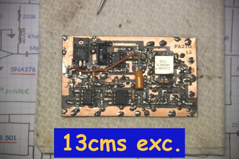
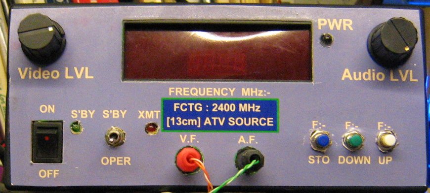
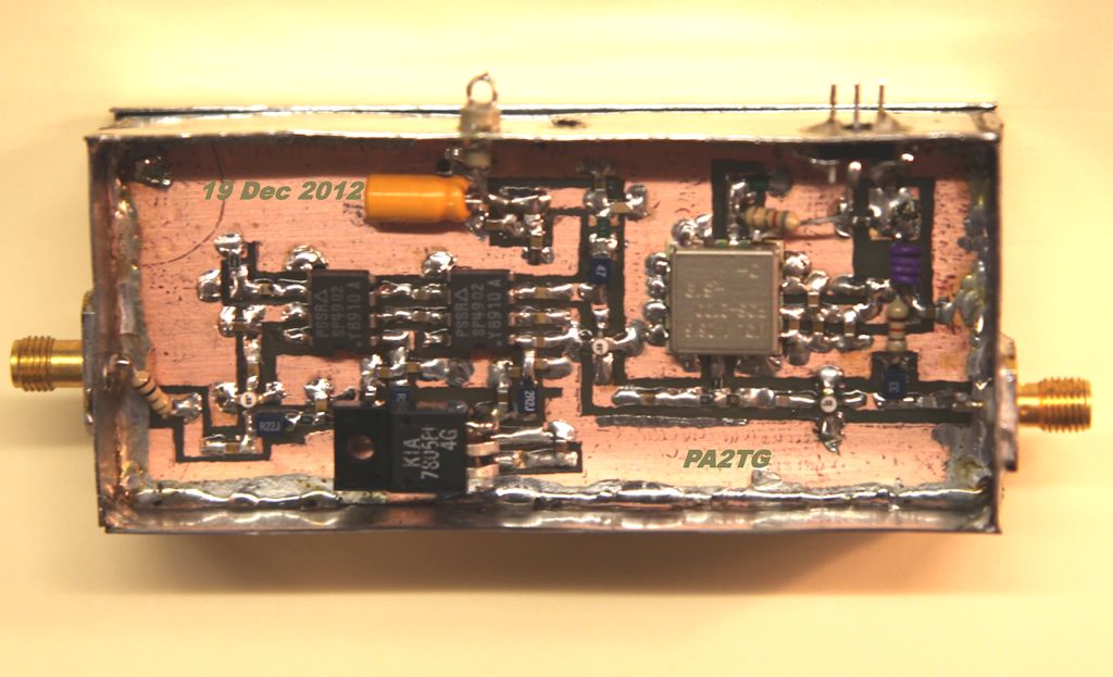
I am now also on the 13-cm band on ATV, this starts off with an exciter unit
which also includes some switching and makes use of a fairly-modified module
which can be bought here for ATV use and provides a couple of tens of milliwatts
of F.M.-TV and audio (I have chosen 7.2 MHz for main audio carrier). This unit
can be seen below:=
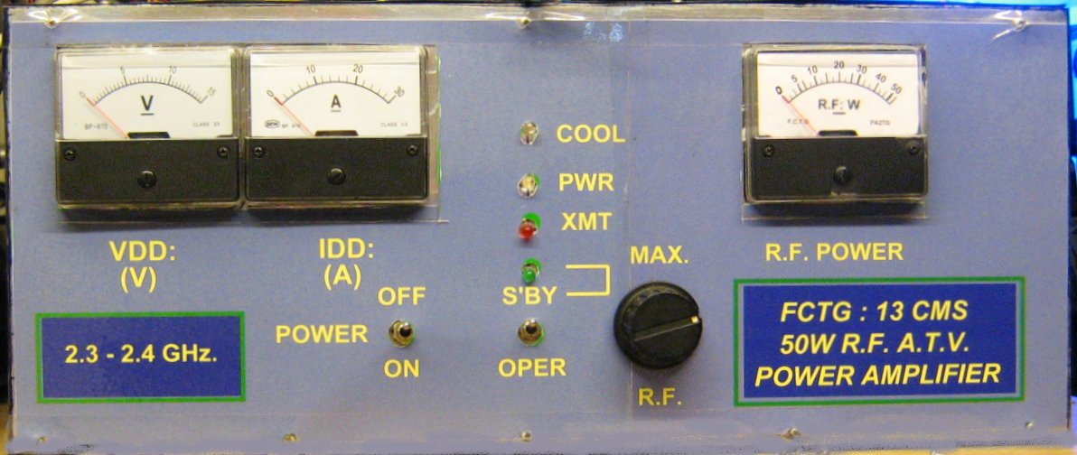
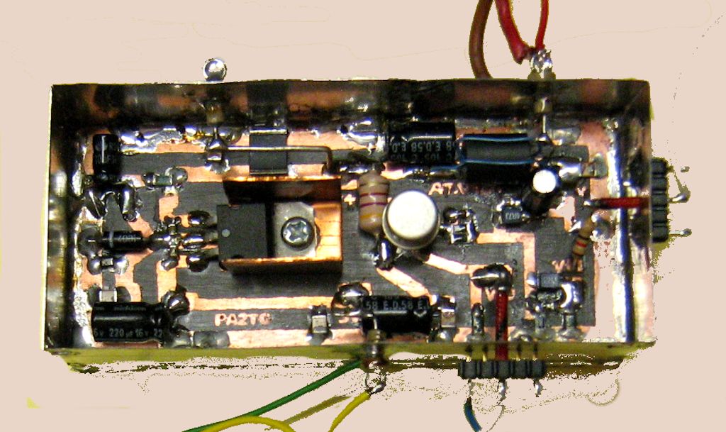
It is followed, not by a driver amplifier, but by the final power amplifier
which is adapted and modified from an ex-telecomm unit with a separate power
supply:-
and this unit developes some 50W into the load at 2330MHz, sufficient for the
time being.
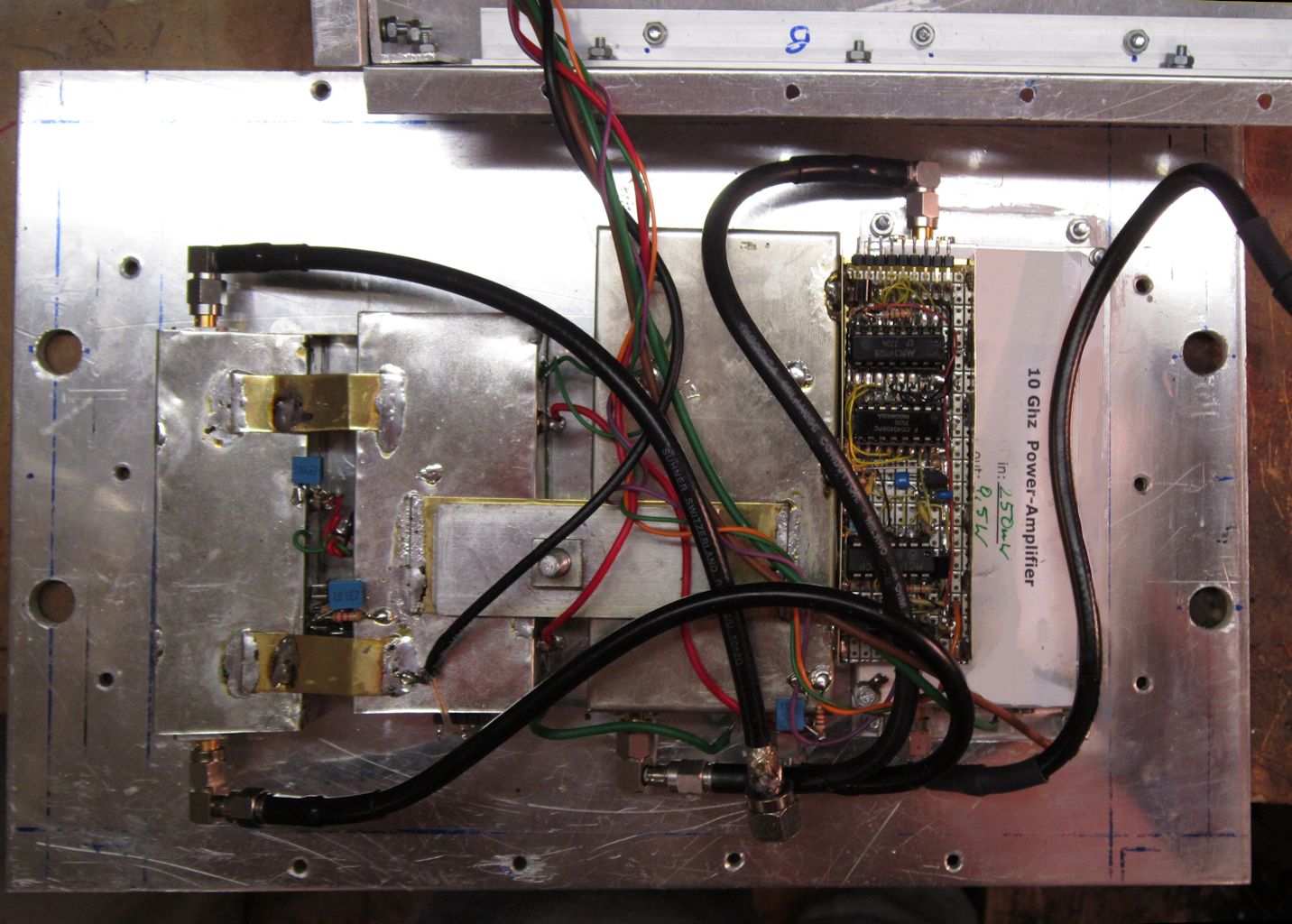
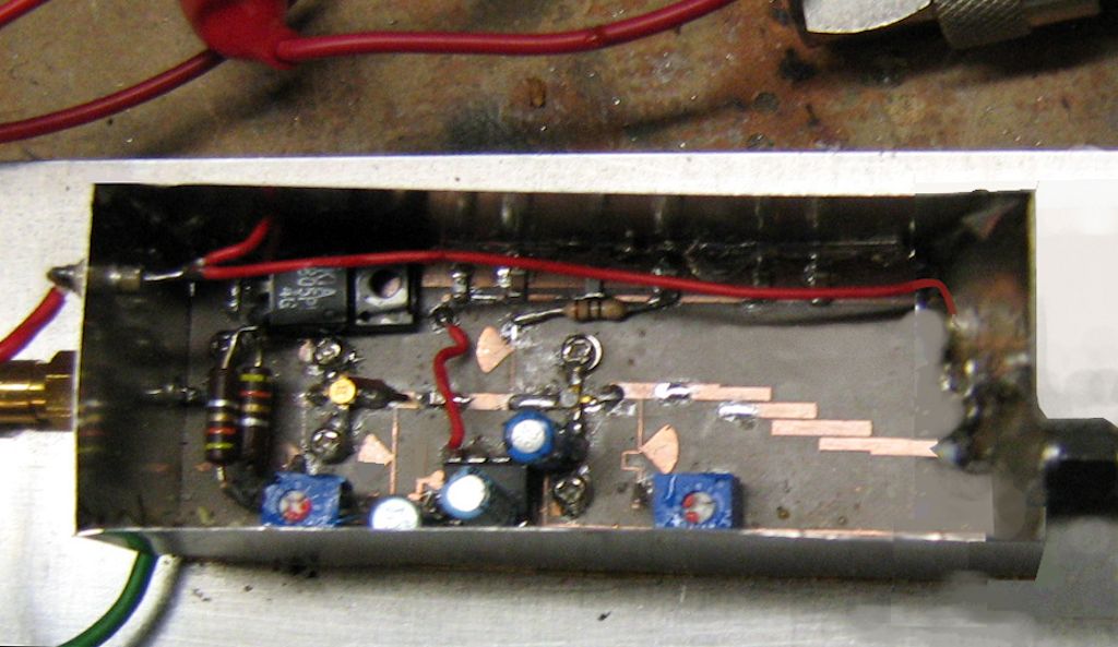
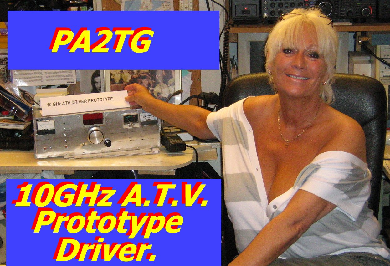
The 3-cms band is also now constructed for, and the main unit together with it's horn
antenna is FINALLY MOUNTED ON THE the mast! At this frequency, the main transmitter
electronics as well as the receiver LNB have to be located on the mast since
cable losses prohibit feeding this from a unit in the 'den'. This means the
design and construction not only of the main 10 GHz parts but also the frequency
dividers and power supply regulation and switching and so on to allow the unit[s] in
the 'shack' to fully control these transmitter and receiver facilities, an example
of which would be the frequency-divided feed down from the mast-mounted transmitter
unit to allow a PLL (phase-locked loop) operating from a reference frquency to
derive a voltage for returning to the mast unit to achieve full transmit frequency
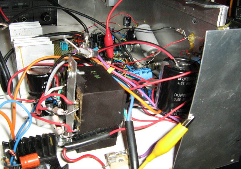
control in addition to video and audio subcarrier modulation signals. A couple
of images of the prototype for this transmitter unit, without it's weatherproof enclosure,
can be seen below:-
Also here are the main units ready for that long day (over 10 hours!) to be mounted
on the mast, the last photo shows the transmit and receive horns fixed:-
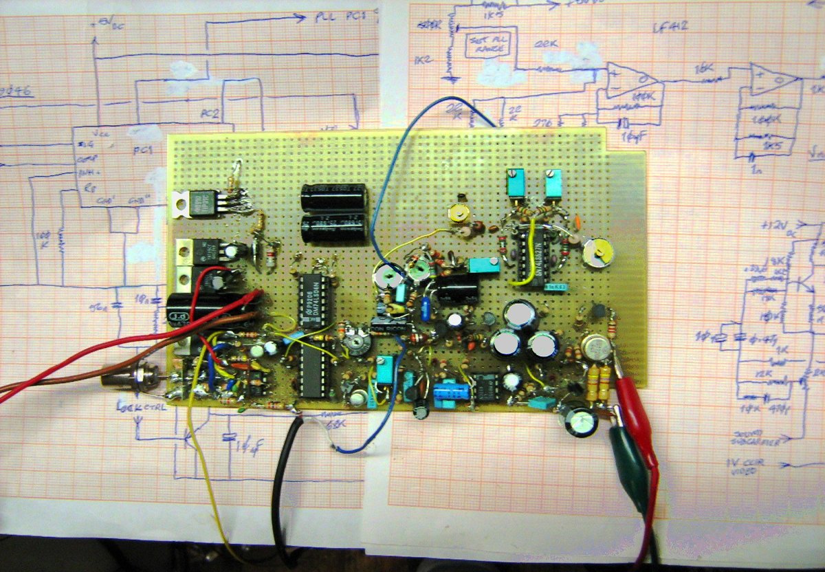
SO, all the 'outdoors' units and activities are (hopefully) completed, with a better colour
horizon camera from the 10 GHz place as well, and now it is down to finishing
the 'indoor' units and putting them into the appropriate cabinets. A lot of
prototyping inolved on the workbench, as can be seen from the folowing, first
the PLL and modulation gerator and control board, and integrating it:-
THE FIRST ECHO TESTS HAVE BEEN DONE AT LOW POWER ang the results, without video
compensation (which is needed) can be seen below:- NEW VIDEO!You can see
here as promised a (short) 10 GHz
test video, the first full 3-cms test video used live, the photos and clips were
only made a couple of weeks ago (it's 27th June now), so a more extensive video for this
band has been produced and will be linked to here shortly.
The ATV capabilities also include the 10GHz (3cm
wavelength) band monitor receiver (not to be confused with the main receiver
for this band) - and some interesting experiments did indeed show
this to be a very useful feature. There are a number of ATV 'repeaters' here in Holland,
as there are in most other countries, and it is most useful to be able to observe ones' own
signal as received by a number of others, with no delay, far better indeed than
the alternative which is the (delayed) relay of *some* of those repeaters
via the Internet on Web sites.
So my own antenna, a smaller gain horn, to place in front of the 10GHz
receive LNB and I did some serious mounting work such that this
antenna can be rotated on it's own (at the same height as the main mast
erection is at) with no relation to the main set of antennas which is on the
main rotator. All of that gave me the appropriate aches and pains from the screwing
of tight fittings, doing up nuts, etc., as good, firm construction is absolutely
necessary. However it was at the time a fine
and sunny day for doing all this (until it got dark at the end of the evening!!!)
and it was something very satisfying to do.
THERE IS NOW A SEMI-LIVE
SET OF VIEWS OF THE STATION ACTIVITIES, especially aimed at the ATV side of things,
this can be seen HERE!, when the active
vies are switched off, the old/last ones are displayed. A totally live stream
will shortly be available on another server, I will tell you when this is online.
I have also built a monitor-and-DVD
switching unit which allows me to record what I receive from other stations
and play that video back to them. You can see a view of my radio
/ ATV station
when they are 'LIVE' by clicking here . These views will be updated as and
when I have the time to devote to the web site, which is not as often as I should
but as some people know I am often very busy with other things.

I've decided to build a reduced version of this processor, for use on the receive side,
to make the most of live ATV received from other stations as well.
You can view it (it is approximately 4 minutes long)
by clicking this link here.
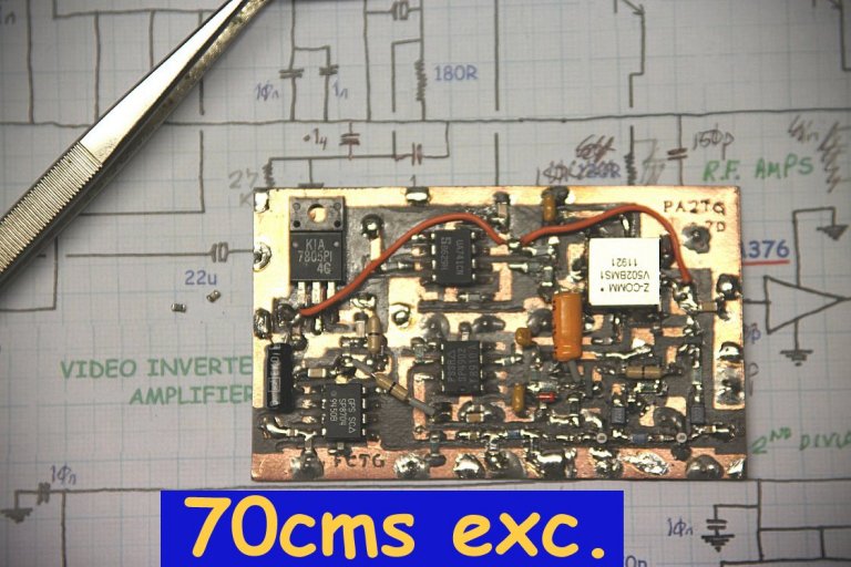
For 70cms (434.250MHz main) we have an audio subcarrier of 5.5MHz as is the
standard over here in this part of Europe, and this is F.M. with typically a
35 - 40 KHz deviation, which together with the video is modulated as A.M. such
as the standard T.V. broadcasts by the exciter unit. This is followed by a
nominal 15-watt driver unit (actually delivering some 18 - 20W), which uses
a much-modified 480-MHz linear board and which also contains a R.F. power
control based upon the use of PIN diodes.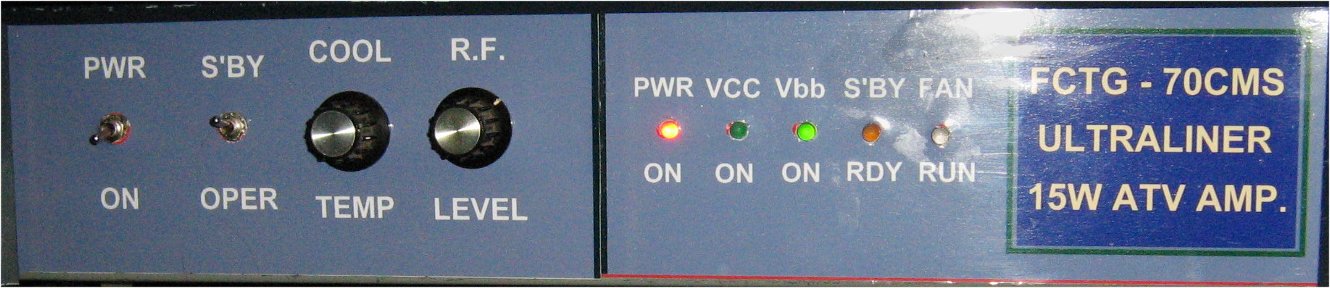
On the receive side, many amateurs use a modified television, tuned down to
434MHz, with a FET pre-amplifier. I also have this available but I have chosen to
design a separate 70cms dedicated ATV receiver 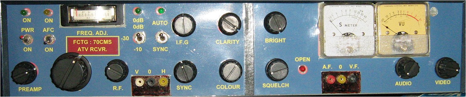
This is followed by the driver unit, which contains a PIN-diode power control
(similar in principle to that I incorporated into the 70cms design), the output
of which is delivered to a Mitsubishi M67715 1.2-watt module designed onto
the driver main board; this in turn drives (currently) an RA18H1213G 18-watt
device which is essentially a 3-stage FET-based power device also on the
main board. 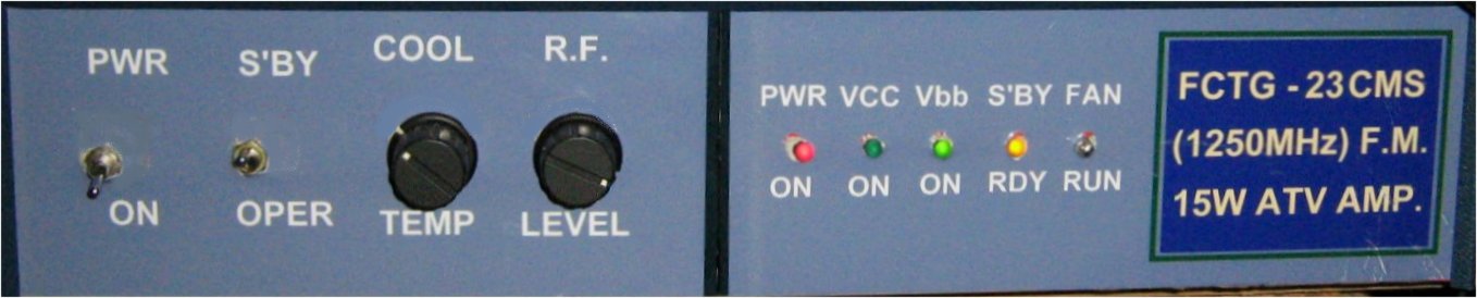
On 23cms for the receive side, use is made of a modified satellite-receiver
tuner which has an intrinsically-linear voltage-dependant frequency control (This
receiver has actually been superceded by a newer unit just out of the workshop!).
This unit (the driver unit) is the most important one indoors for the 10 GHz
ATV functionality, for it contains the PLL, the modulation signal inclusion,
and the return drive generation for the mast-mounted transmit generator
circuitry. As you were able to see, the prototype of this unit is almost
complete.
The more recent ATV test video is produced (there are even more different
videos now), the one here is a common one and can be used on any of the bands I use) and the Web
version IS AVAILABLE HERE. A new one is under production right
now and the Web version will be available once this production is completed
shortly.
Included here are some older examples
of what I have been able to transmit and monitor:-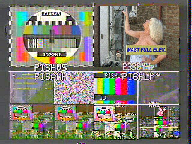


There will also shortly be a new test video, taking
into account the new 10GHz / 3cm facilities and with some of the new gear for
that band whis is being modelled.
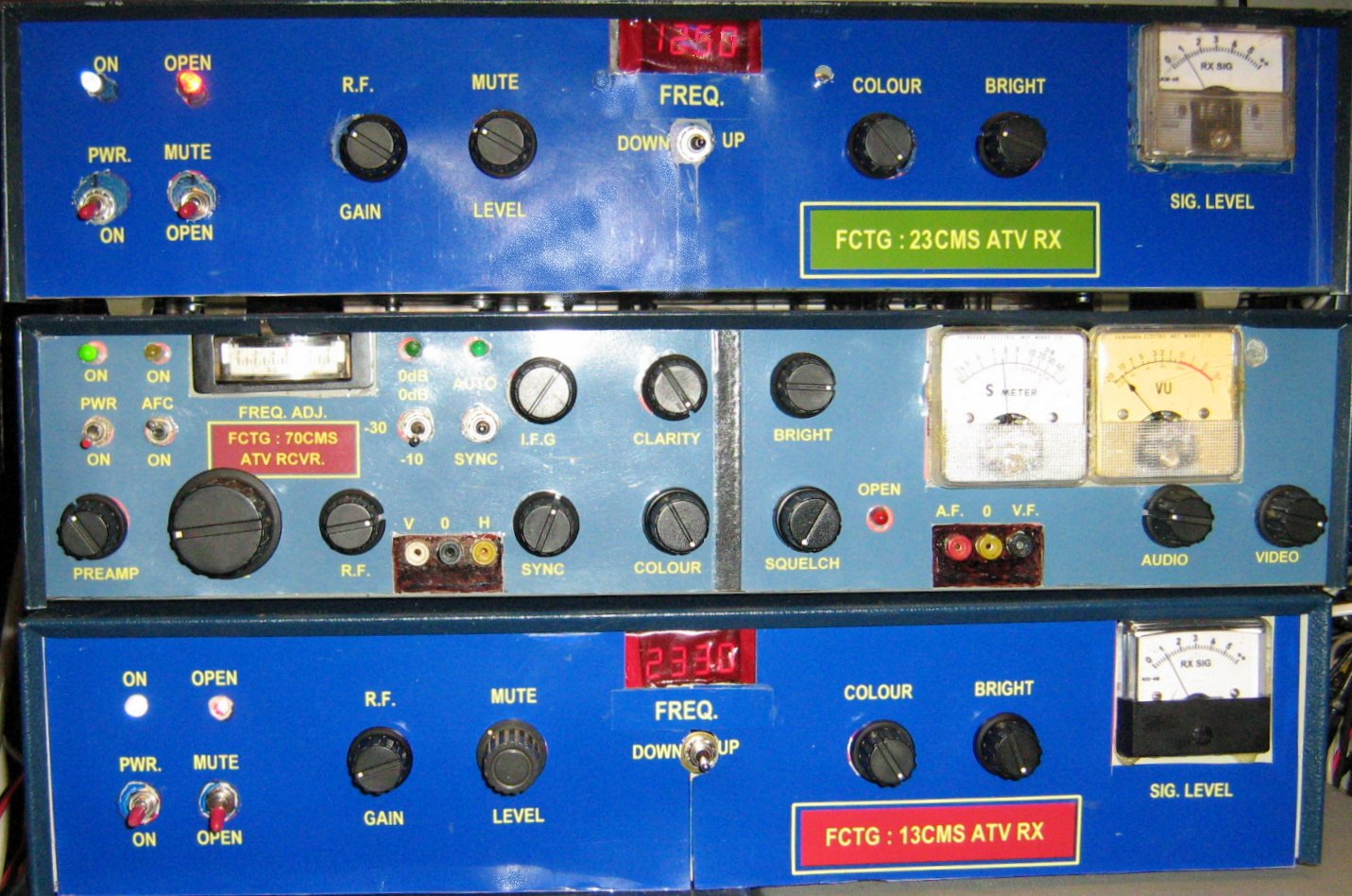
There is also a new ATV set of receivers, of my own design, for 70cm,
23cm and 13cm which do perform to my satisfaction:
So, all in all I am satisfied with the work done despite other problems
that have beset me over the last couple of weeks.
 You can E-mail the
author of these pages (Trevor Gale) by using
this link, or by sending mail to tgale@tgale.net on the Dutch Internet
service provider XS4ALL.
You can E-mail the
author of these pages (Trevor Gale) by using
this link, or by sending mail to tgale@tgale.net on the Dutch Internet
service provider XS4ALL. 