PA2TG (Trevor Gale)'s Station News Page.
The latest news from PA2TG (me, Trevor), updated here in this
page on 30th March 2015 in the evening local.
A number of you have asked about file sharing in a home network and a few are running either Linux or Windows or both: some folk have had some problems getting this running, so I've put together a quick introduction to Linux <> Windows file sharing in this page here (fileshare.html) which shows some of the details of getting it running: *NOTE* this is a 'quick and simple' way of implementing it although I've covered a few different situations - I recommend you choose the bits of that page that you need, and also enable the security features you require such as SELinux and firewall(s) since what I show is very 'open' just to keep the content simple and focussed.
Many Radio Amateurs need to occasionally source some electronic components, or even complete units of equipment or a 'rig',often via the different online Web outlets - and that often involves receiving shipment through a courier to deliver your package(s). So here's a 'warning' for you when expecting such a package from a courier, i.e. DHL Express.
My latest experience of DHL Express Netherlands (a colleague suggested "Delay, Hold, Lose.") is one I actually took the trouble to keep notes about. I have never experienced such appalling and disgustingly rude behaviour, you should read my description on the page I put up about it - http://tgale.home.xs4all.nl/dhlcourse.html (  you can view it here, screenshots and all) - it is a catalog of worthless, careless performance, lack of service, lies, and unbelievably rude behaviour. Unbelievable!
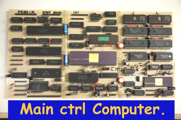
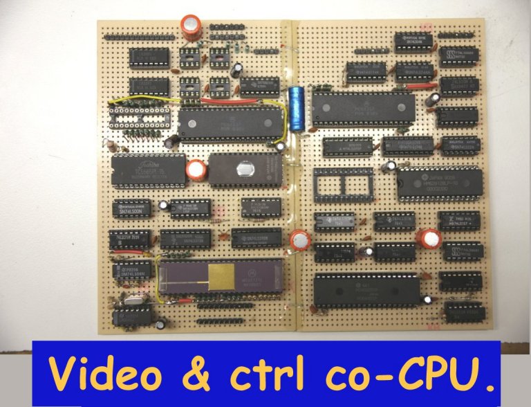
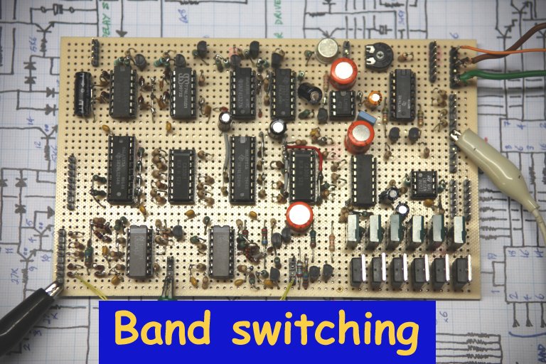
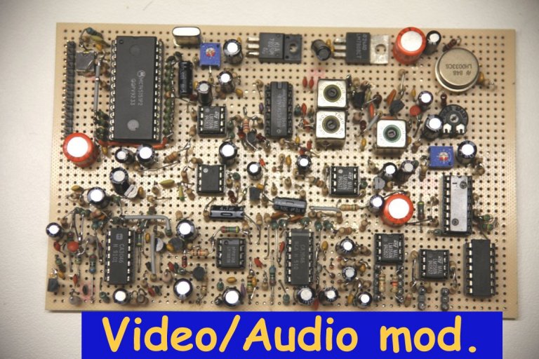
Well, I had already (a couple months ago) decided that instead of building "yet another box" for the
next ATV band (6 cms) that it would be better to get a bit cleaner in orgasining the whole ATV setup
instead of having things in so many places - so I've commenced the design and building of a full
dedicated-computer-controlled 6-band ATV main rig. One more board is complete as of this day, and
the next work is probably centred around the case / housing for the rig and the 5.6GHz antenna.
The design of it all is 99% complete, and I am
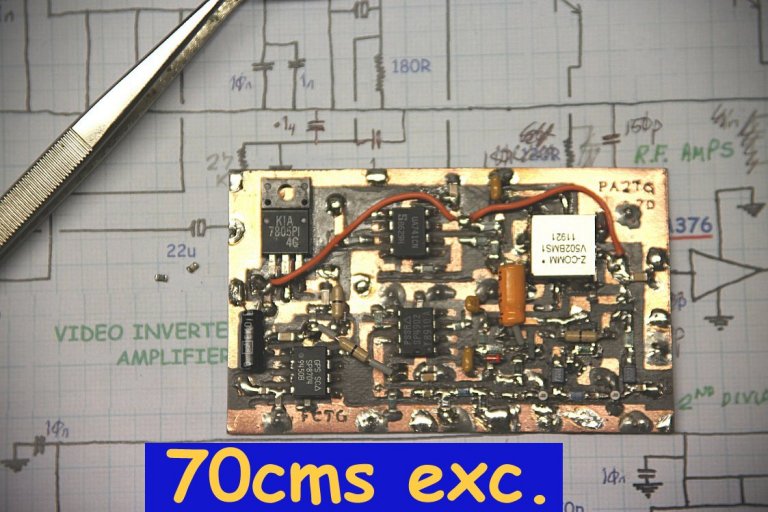
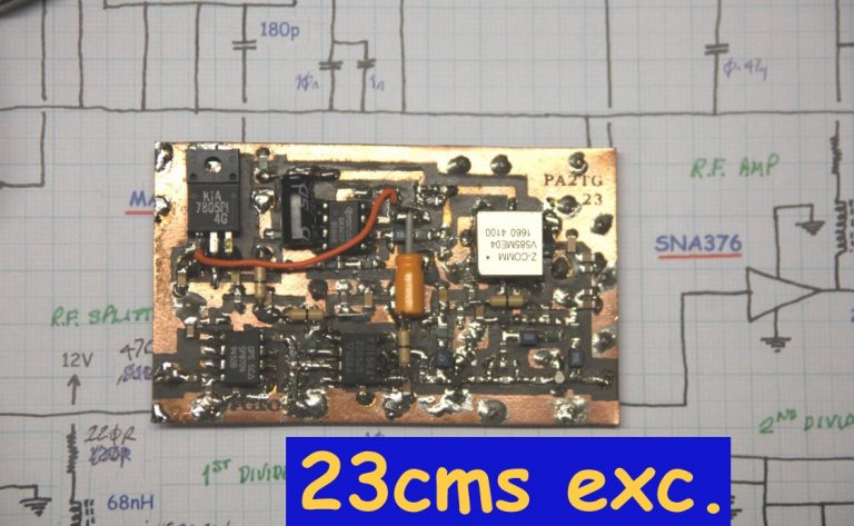
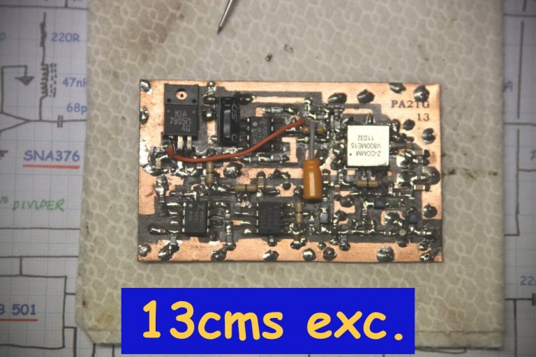
well on the way in the building process; it is a rig for 70cms, 23cms, 13cms, 6cms, 3cms and 1.2cms
(for 6cms, 3cms and 1.2cms the final multipliers and power amplifiers plus the preamps and downconverters
are located in mast-head units).
There are a few photos of the progress in the workshop for this rig below, and it is to be noted
that since the overall concept allows it there have been quite a few 'extras' and features that
I have brought into it which means that the overall project is more than twice (!) as much work
as I had originally thought it to be - but hopefully it will be well worth all the extra efforts
and perspiration that's involved.
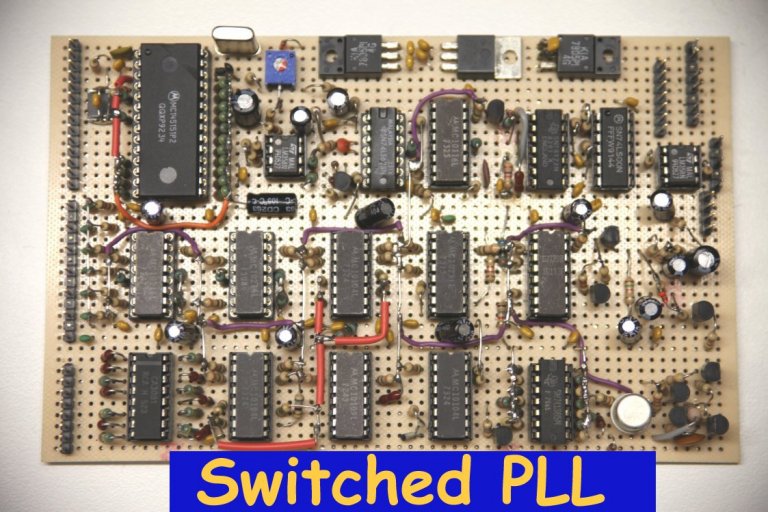
Basically the rig comprises a central dedicated computer system (around a 680x0-series CPU) which
handles most operability and the user interface and control, a co-processor CPU unit which is
dedicated to intensive video generation and control, a switched dual-PLL which works for all the
bands, a video and audio control / interface unit with an on-board sound-subcarrier PLL section,
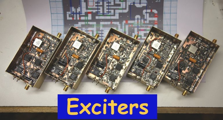
exciters for each of the bands which take the PLL output for frequency control and take the
control / interface outputs for modulation, a video sources selection board, and a power control
unit with an incorporated sequencer for TX/RX switching and timing. Obviously there is a
comprehensive control panel and display interface together with such features as masthead
telemetry (as I first implemented in the existing 3cms rig), multiple band and setup memories
(including items such as modulation width, subcarrier frequency and the like), R.F. power
monitoring & display, power-amplifier and temperature protection.
The overall unit housing has yet to be built but the dimensioning and layout is basically already drawn up and the display and metering I've decided upon and am planning into the panel. The whole thing can be operated from the front panel but is also comprehensively operable through the use of a video window or an external serial link to (e.g.) some desktop or laptop P.C. or even a tablet computer over a network. Just a few photos of some boards or units are shown below for an idea of what is going into this unit:-
And from the annals of memory...
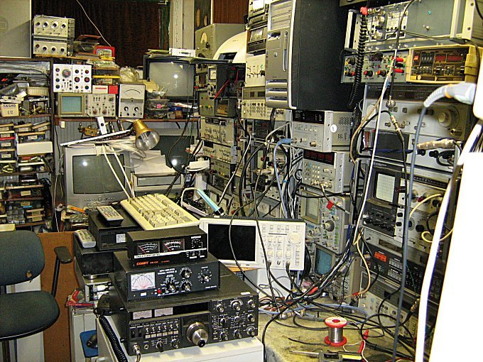
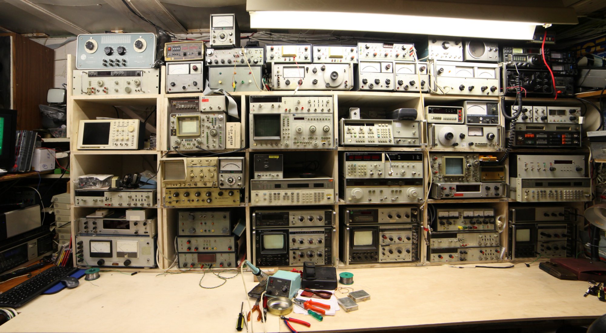
Last years' return from the sojurn in Switzerland I'd already thought it was time to sort out the electronics side of the workshop working area and its instrumentation, and that took a couple of weeks of hard work what with new benches and placing newly acquired equipment, all in a more orderly and streamlined manner. As a reminder (ugh...!) this is an idea of how I'd become 'hemmed in', restricted by the too-quick adding of extra equipment as it arrived and was needed:
So as you can see what I mean....
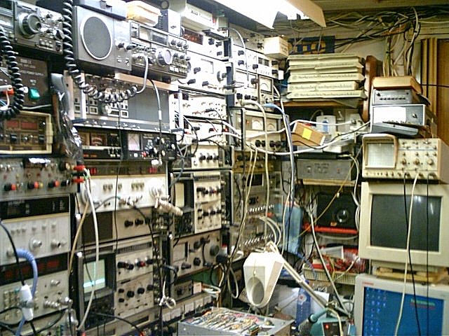
....which meant that I was effectively limited to working on things in a space like a telephone box, and walking around various equipment even to go fetch a few components from the end shelves.
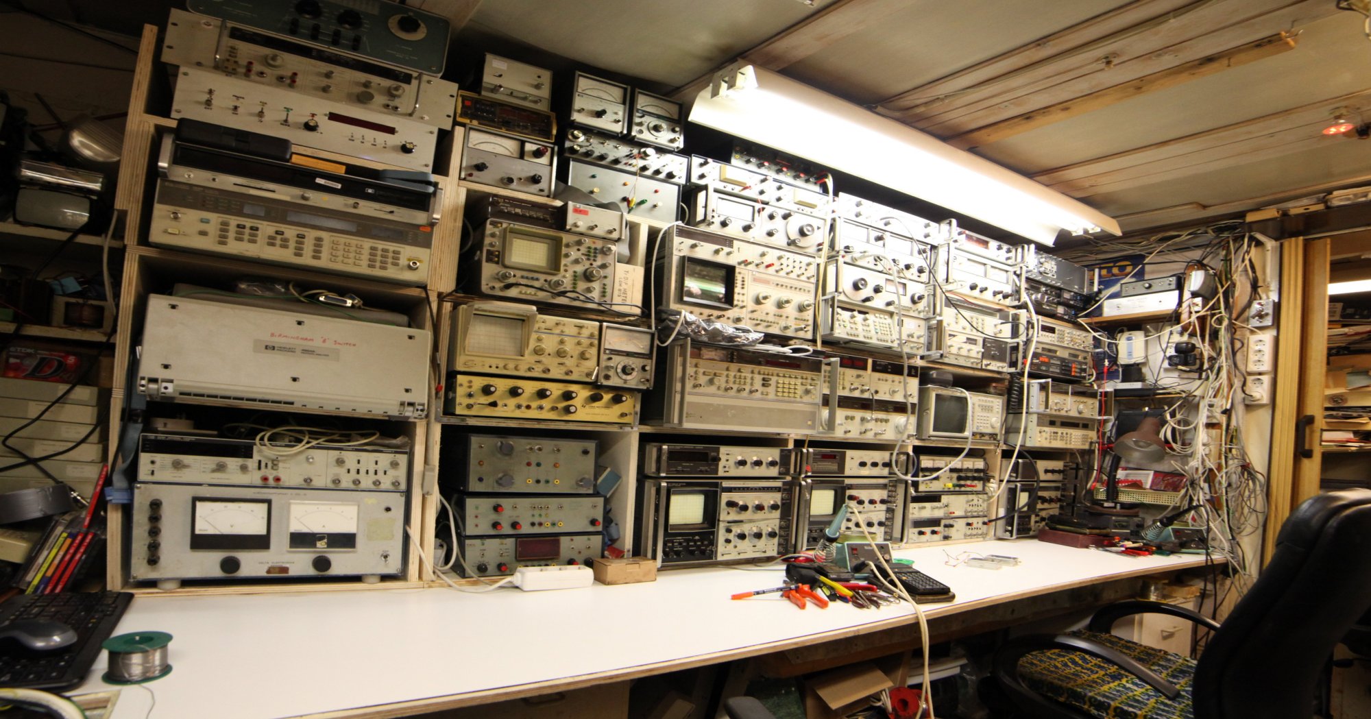
So here's just a couple of quickies here as photos of the new layout. The first 2 are of the electronic working area with most of the instruments placed; the next 2 are how that is finalised and with the new working surface laid as a clean working surface, and a few more as we carry on.
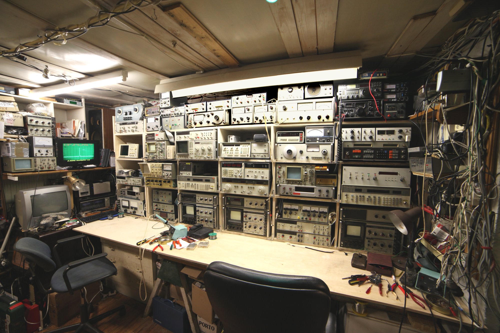
The final layout and working bench:-
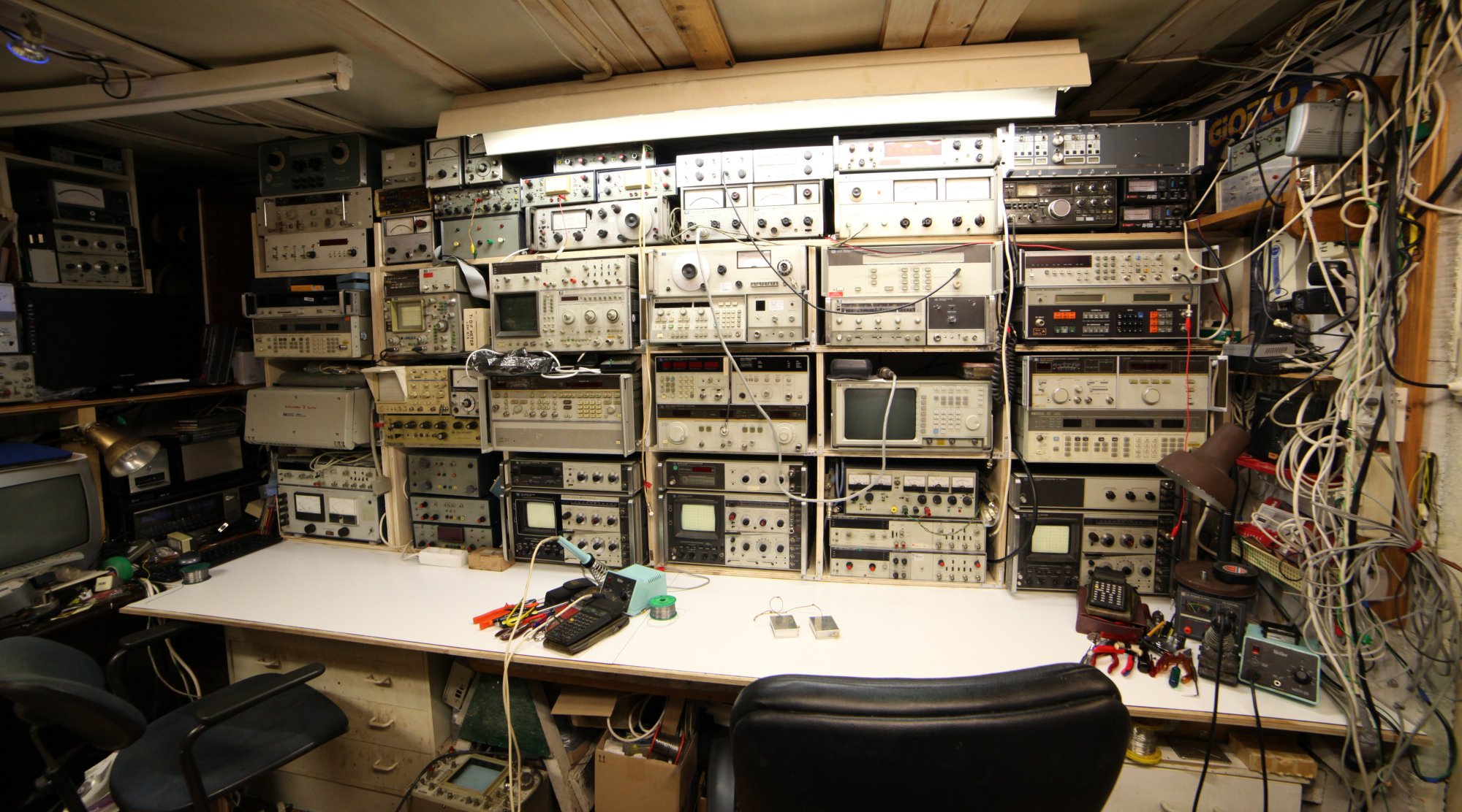
Next is a general view of the whole workshop roughly from the entrance:
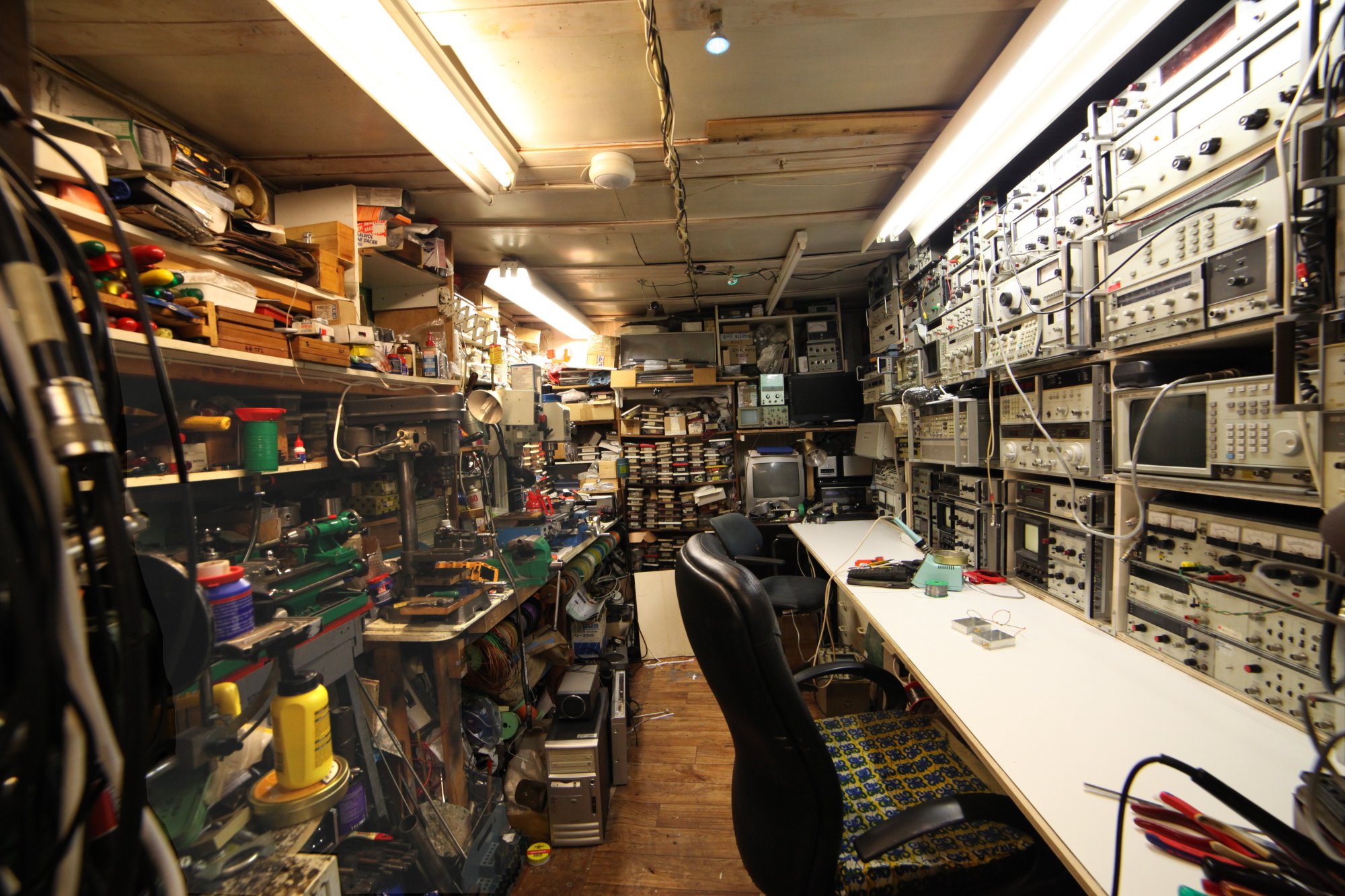
The following two are [a] the mechanical 'side' of the workshop, with its lathe, drill,
milling machine, grinders and so on, and [b] the electronics 'side' as it is now laid out,
all viewed from the entrance to it all.
So here goes:-
The 'mechanical side' of the workshop has already recently been somewhat re-arranged, so much of that remains as it was for a few months, as follows:-
By the main entrance to the workshop and shack there's now a drawing/design desk:-
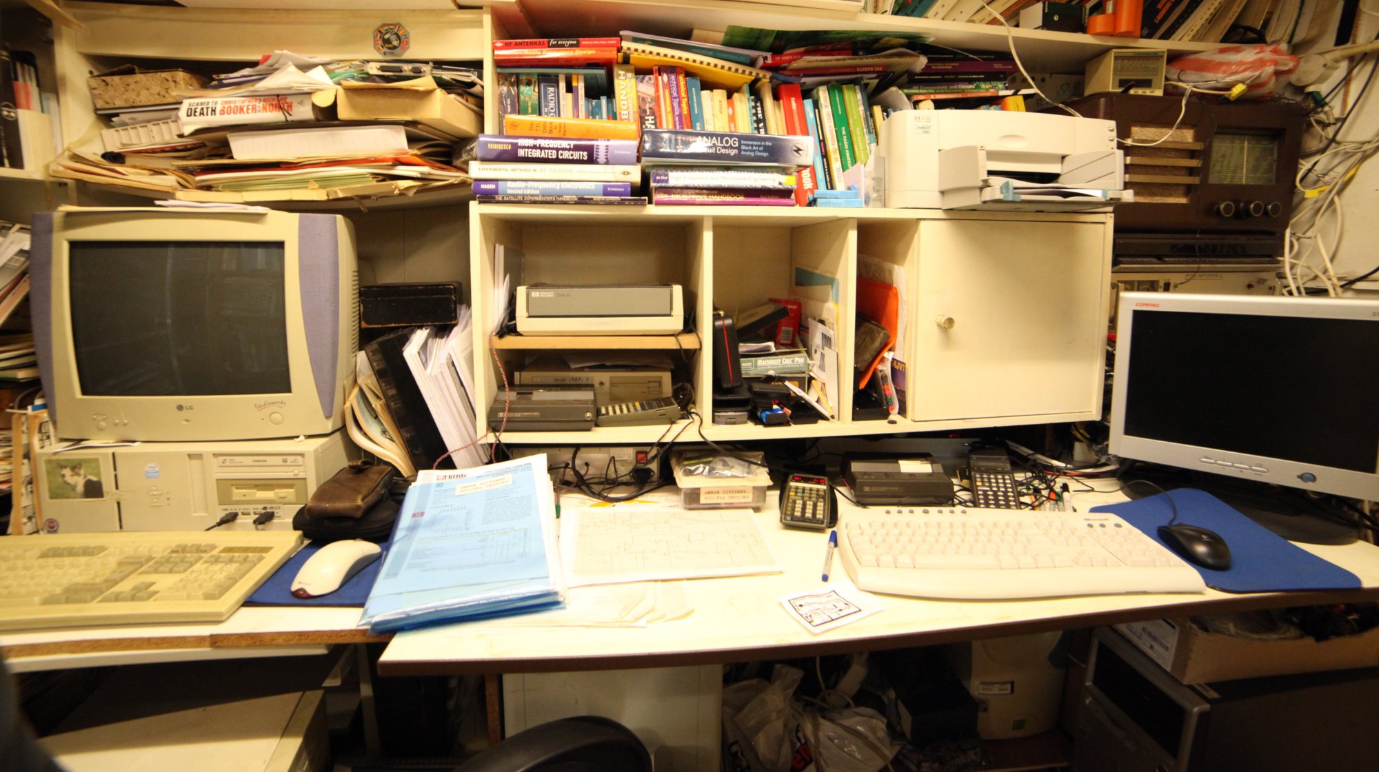
and behind this (not seen here) there are a couple of shelves of data books of both analog and digital devices as well as the necessary R.F. and microwave references.
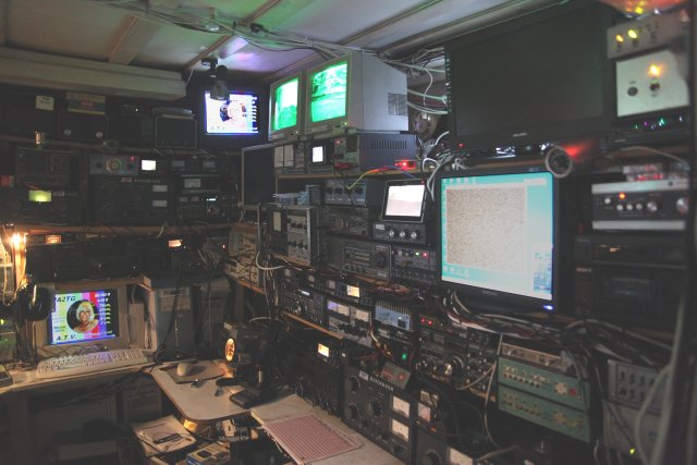
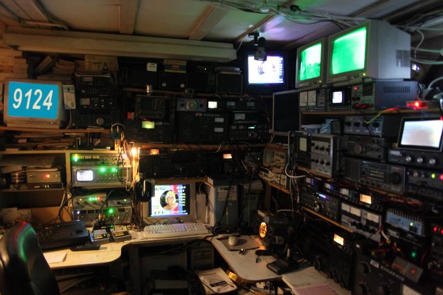
To finish off, seeing as I had the camera to hand anyways, here's a couple of the shack - beginning with the main operating bench:-
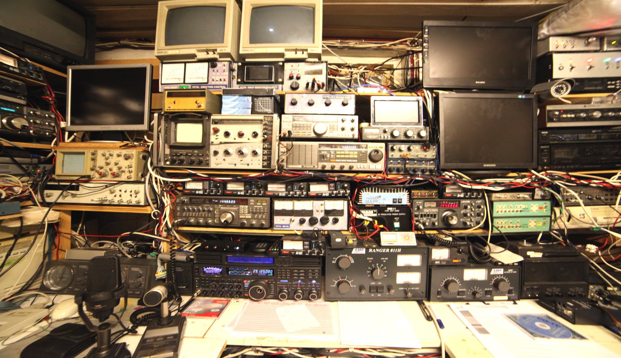
...and the further operating area to the side of that...
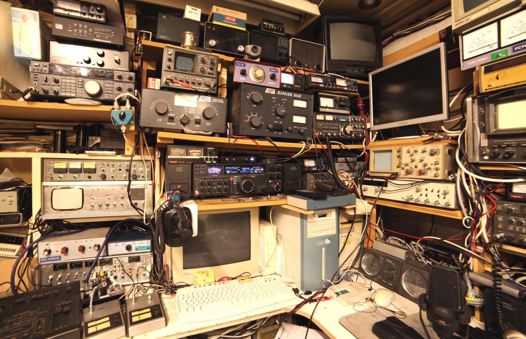
So finally a quick peek at a couple of the ATV units, opposite the main operating area:-
So that's enough re-organising for me, hopefully for a few more years (!) - however all of this has meant that the progress on the 5.7GHz / 6cms ATV transmitter, receiver and antenna has been put back a little, and I very much doubt that I shall be active on 6 cms for the last 2013 ATV weekend in December since it's only a fortnight away; I shall instead vow to begin 2014 with the inclusion of 6 cms and a re-arranged antenna deployment in the mast.
Well, previously, the activity as of September 2013 was in two main "bits" really since I was
not only been busy with the radio/electronics side of things but also on the necessary mechanical side, since as
many of you will know once work is considered at microwave frequencies then a considerable amount of metal
warking becomes involved.
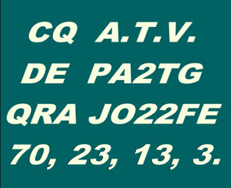
However, last things first and the ATV Weekend a few weeks ago completed and I'm happy to be able
to report contacts on 70cms / 434MHz, 23cms / 1.2GHz, 13cms / 2.3GHz and 3cms / 10GHz. Some of those contacts and
reports I hope have been saved to a parallel DVD that I was running at the time; in the time since I have
not yet had a chance to examine that recording or extract any exerpts for this webpage! Propagation conditions were not
exemplary, but nevertheless sufficient to gain some worthwhile results concerning station performance and
associated information. There's just few photos of the station in action as follows:-
First the two intro and testcard shots sent round the loop for checking:
 ..
..

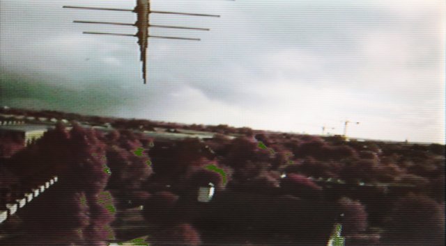
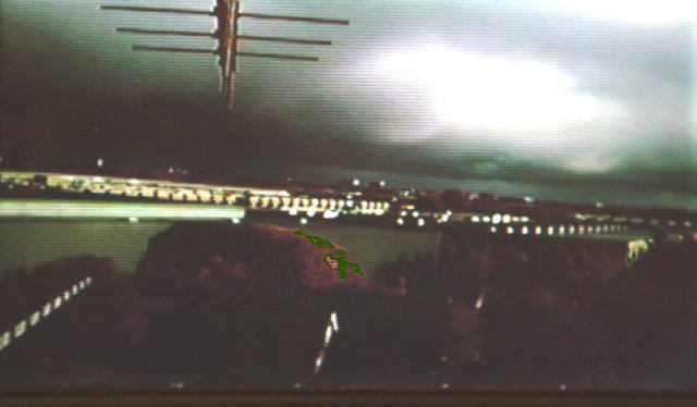
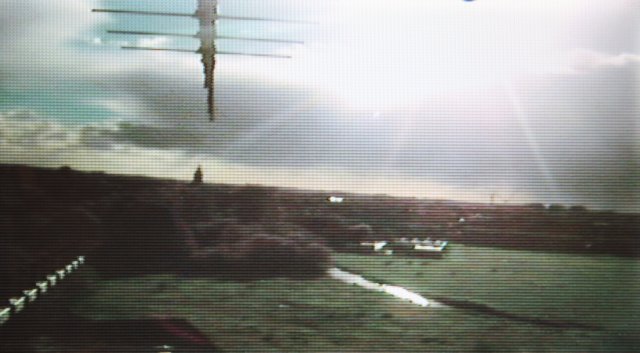
Now, in my antenna mast there are two cameras, one for checking the cable harness and some antenna mounts whilst rotating the stack, and the other to view the horizon as the antennas 'see' it. So for this time, I included a few of the horizon views during the while, as can be seen here:-
 ..
..
 ..
..

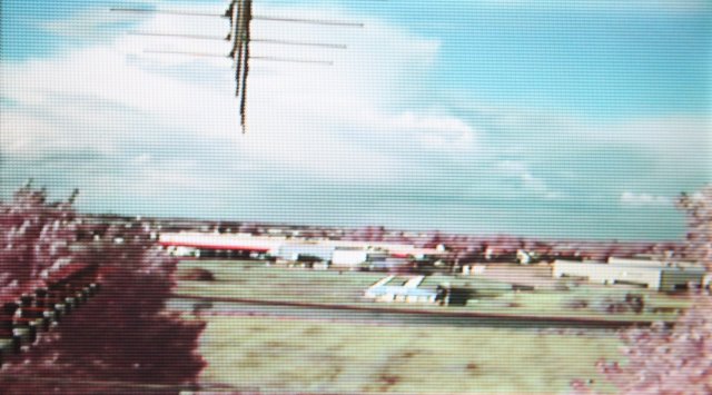
Hopefully they give an idea of the antenna "take-off" from the location here - and an idea of the variable weaher during this weekend!
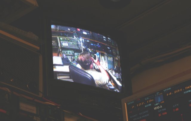
Ang then a couple of the station during the later evening, just to give an idea of the operating situation:
 ..
..
and a wider all-round view at:
Directly on the Sunday after other ATV activity a team here in .NL launched a balloon with transponders, beacons and an ATV feed attached to it, I'm hoping I managed to record some of the ATV feed I managed to view on that DVD I had linked up, but here's the status page as relayed from Ijsselstein and received here on 10 GHz:
It was too busy here to make photographs of everything whilst in operation but hopefully there'll be more of the ATV activity in the next update I do for this page!.
Now, secondly, I mentioned that at the high frequencies in use here at PA2TG I do need to have the facilities to be able to make some of the necessary metalwork involved: for many years I have had an (old but good after refurbishing by myself) metal lathe in addition to a lot of tooling that I have added for its use:
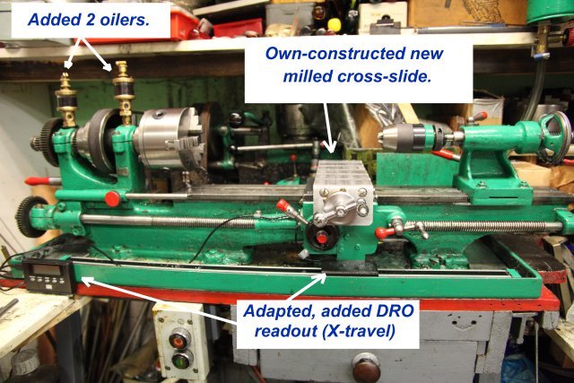
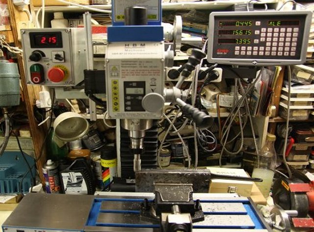
(Yes, it is well in use and this is before the last cleanup!). However I began to think some years ago that I also needed the features and capabilities that a reasonable Milling Machine could offer, and a few weeks ago I finally decided upon a machine to satisfy my requirements and installed that in the workshop. With the advice and assistance of a friend Jos PA3ACJ, who's also a very helpful amateur and has extensive fine metalworking experience, we visited a local mechanical 'emporium' where he encouraged me to empty some of my wallet(!!!) and carry away some heavy metal objects in return! A very enjoyable 'visit' indeed.
The result,
allows me finally to do some of the operations for (e.g.) filter construction, making enclosures for microwave amplifiers, multipliers and so on. Two immediate tasks, however, were actually to make both a cross-slide and a top-slide for that lathe, since the older ones on there were a little 'loose' in use and were difficult to use when doing work of any significant accuracy. Hence rather than following the advice from the shop to "begin working brass or aluminium" for "easier work" I designed and drew out diagrams for both of these items which are made from stock hard steel. Admittedly, I do have prior metalworking experience from younger years which I have never forgotten even if I haven't needed to do much during my career.
If you are a newcomer to metal-cutting, milling or turning using a lathe or a milling machine then take advice or lessons and above all follow all safety recommendations - these machines are not 'toys' and can exert large torques to simply tear off any curious finger or wind up a scarf or tie just as effectively as a hangmans' noose. Be warned. First, then, a couple of shots of the cross-slide (this travels 'in or out' towards the back of the lathe as you would stand at it) complete with T-slots which are to accept other (tool-holding) fixtures to be able to actually cut the work:-
 ..
..
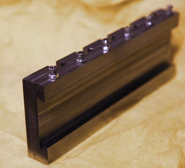
and the view of that unit complete with gib screws and the drive handle with wheel:
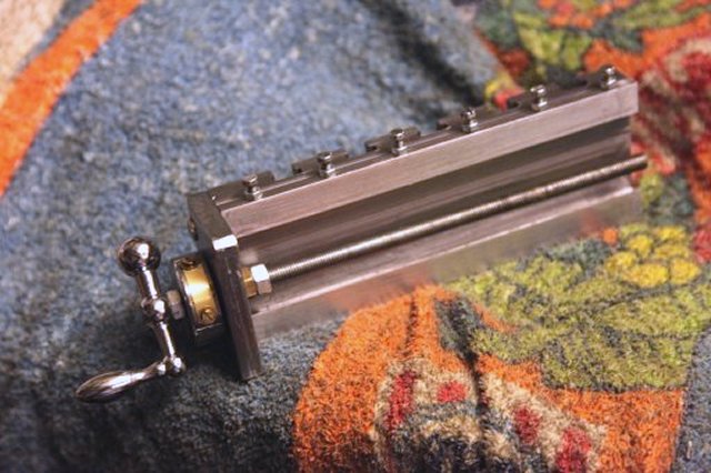
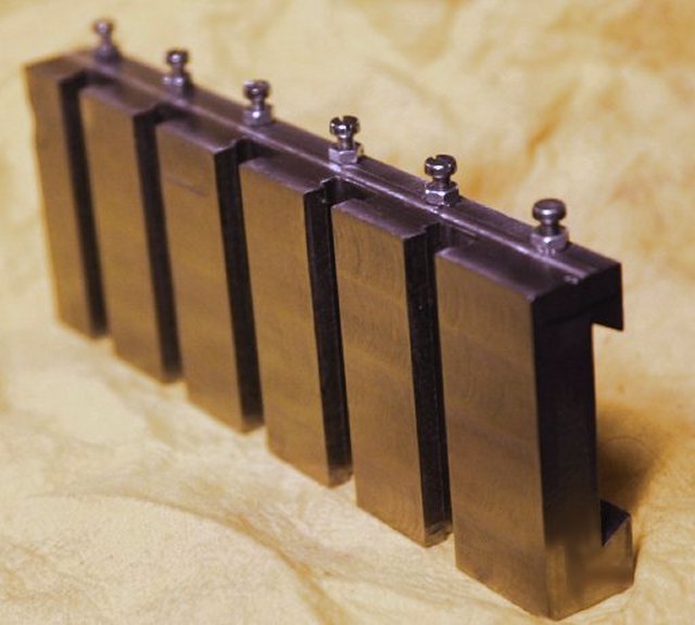
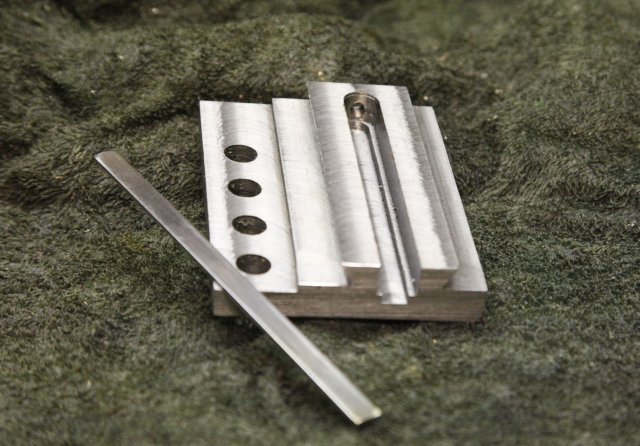
As mentioned, the second item made was the top-slide (which fits on the top of the cross-slide and indirectly holds the cutting tool for the work in hand), this can travel longitudinally in parallel with the axis of the work or instead at a pre-fixed angle so as to turn (e.g.) a taper or a cone shape on the work being performed:
 ..
..
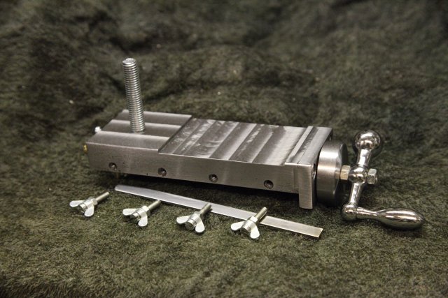
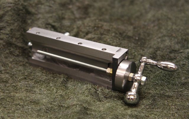
The last two (below) show the top-slide with the gib-strip used, which is the underneath part of the unit, and also the top component of the unit as mounted together with drive wheel and tool-post.
 ..
..
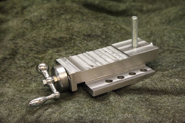
Both the cross slide and the top-slide have already been used, and indeed the new cross-slide was used together with a different tool-post in the manufacture of the scaled drive wheel for the top-slide.
With all of this, plus a needed clean of the horn antennas in the mast due to insect housing (!), the last few weeks of work at the station PA2TG are from my standpoint reasonably satisfactory. So I'll end this update here, more photos of the ATV activities, and of the outstanding 6cms / 5.7GHz units will come in for my next update.
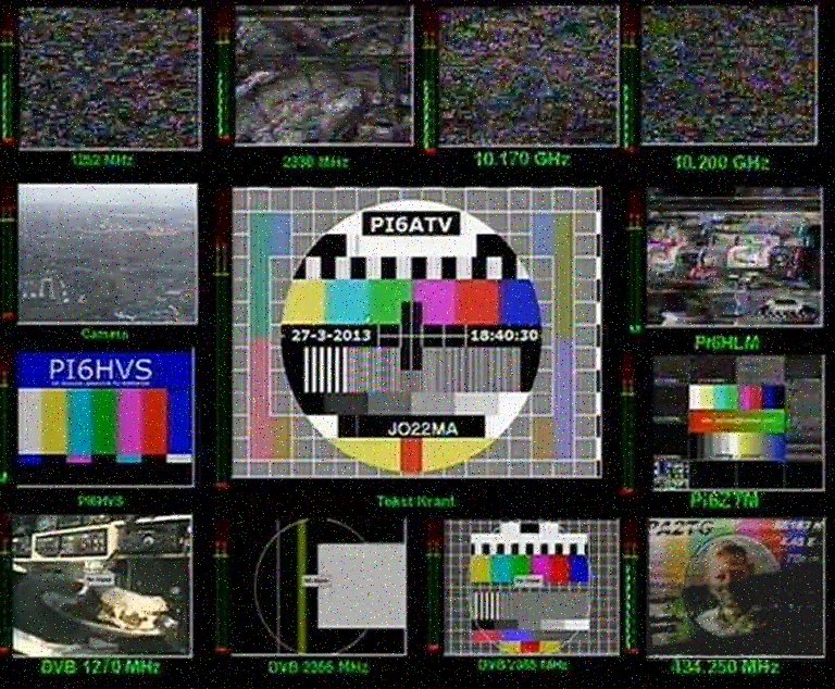
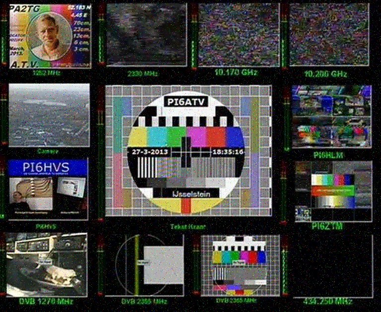
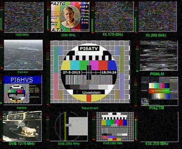
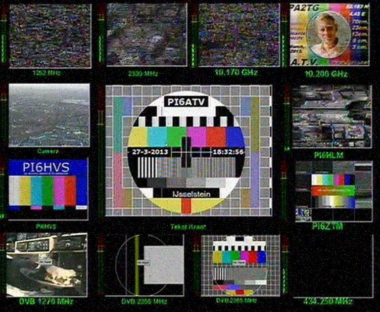
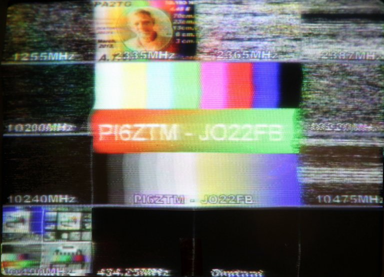
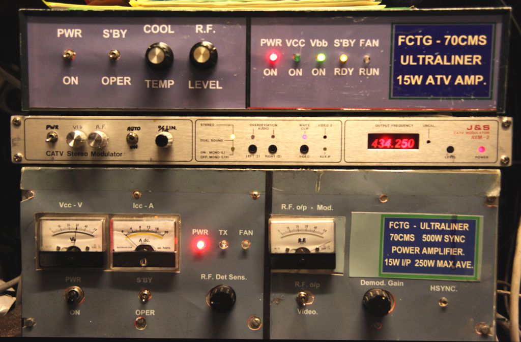
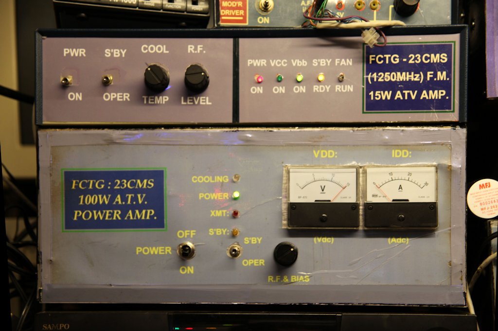
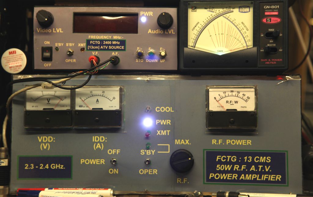
The latest work here at PA2TG includes the upgrade revision of the 23cms ATV final amplifier, which now delivers the 150W and has proved to work well into several of the repeaters receivable here. Using just the "monitor" 10GHz / 3cms facility it's been possible to receive and capture some of the received signals from, notably, PI6ZTM in Zoetermeer (10.150GHz), PI6HLM in Haarlem (10.250GHz), a well as PI6ATV in Ijsseltein (10.475GHz): at the time of this update it seems that the repeater PI6KPN in Den Haag (10.490GHz) is temporarily out of service. Some captures of my retransmissions to these repeaters are shown below:-
PI6ATV with 70cm:-
PI6ATV with 23cm:-
PI6ATV with 13cm:-
PI6ATV with 3cm:-
PI6HLM with 23cm:-
PI6ZTM with 13cm:-
The signals when using my "main" 10GHz long gain-horn and LNB are appreciably better but for this test I dedicated the
main horn set-up to the occaional 10GHz transmit tests. I receive a stronger 10GHz signal from PI6ATV then others using
the monitor horn.
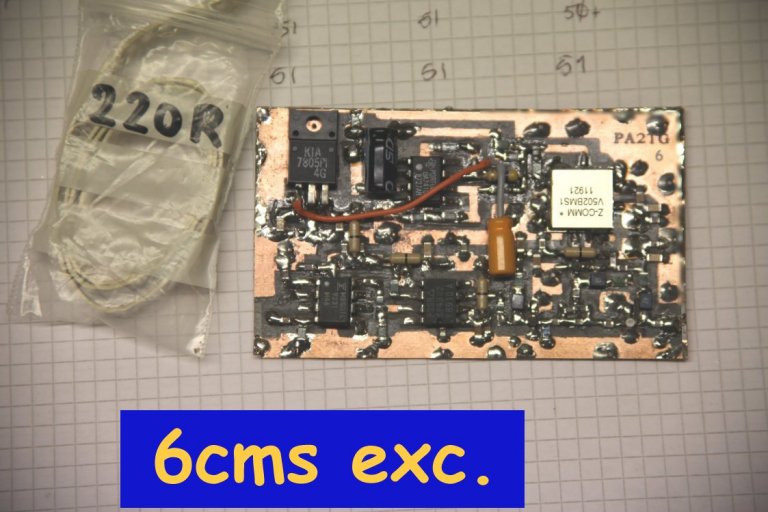
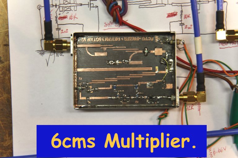
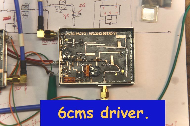
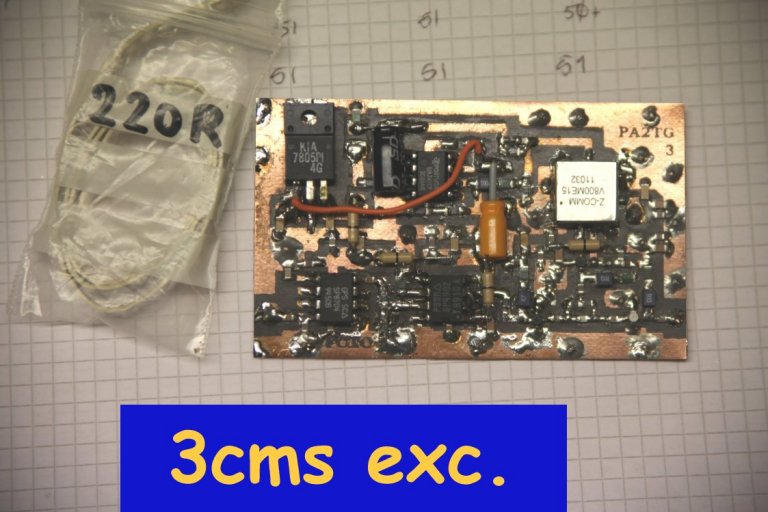
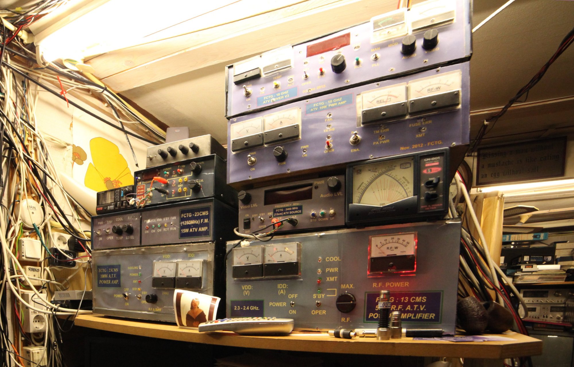
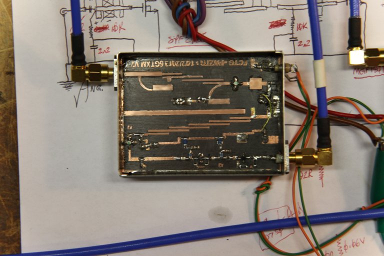
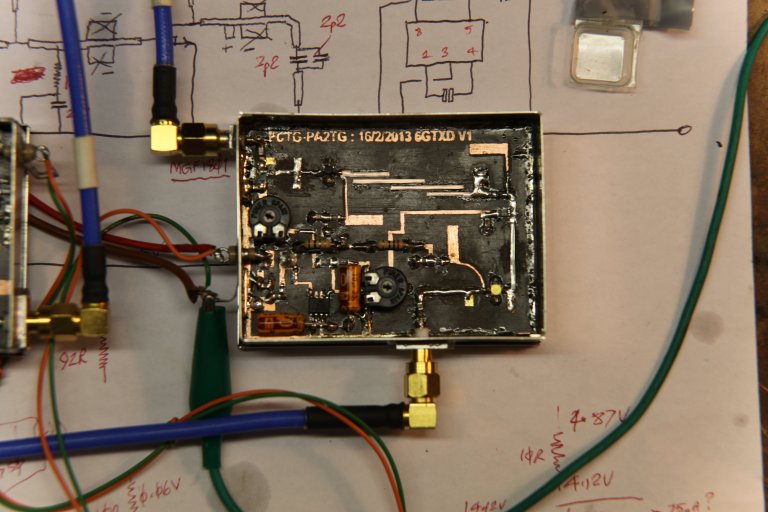
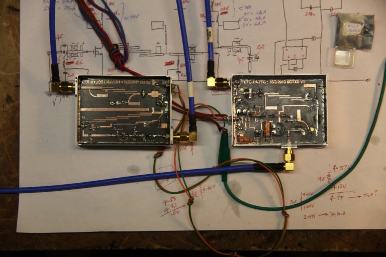
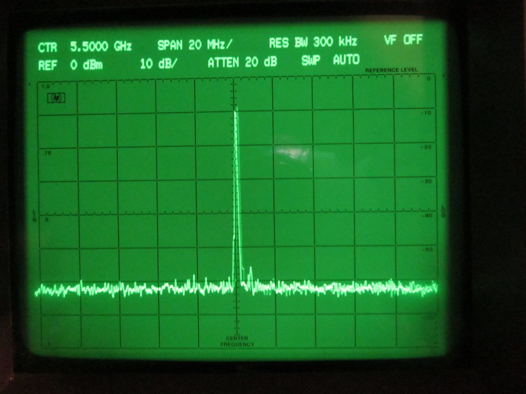
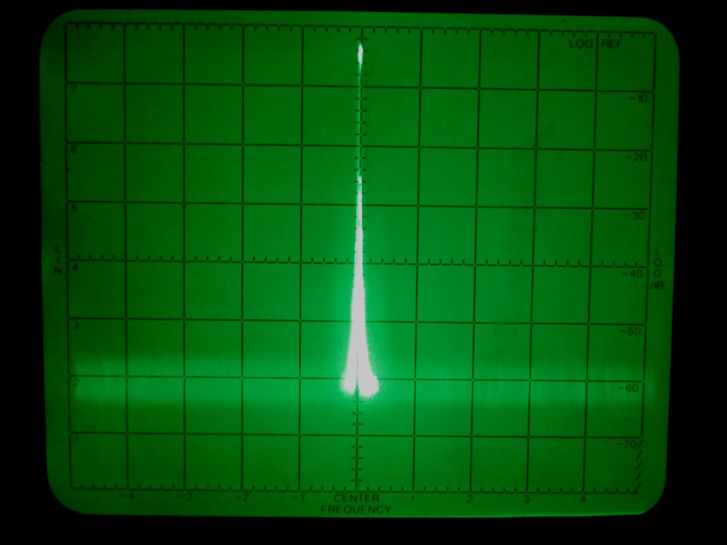
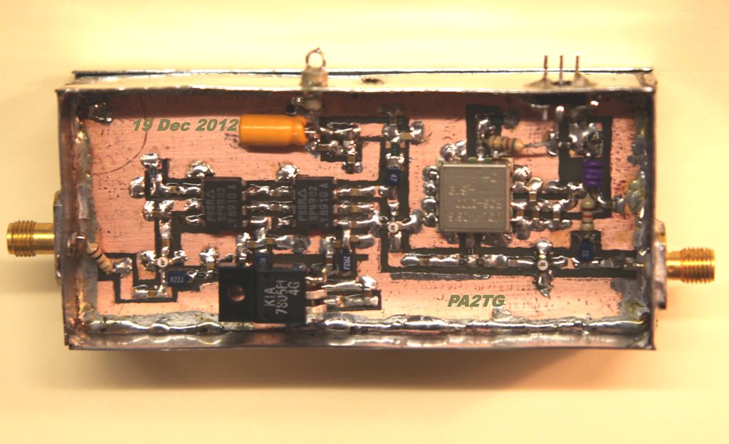
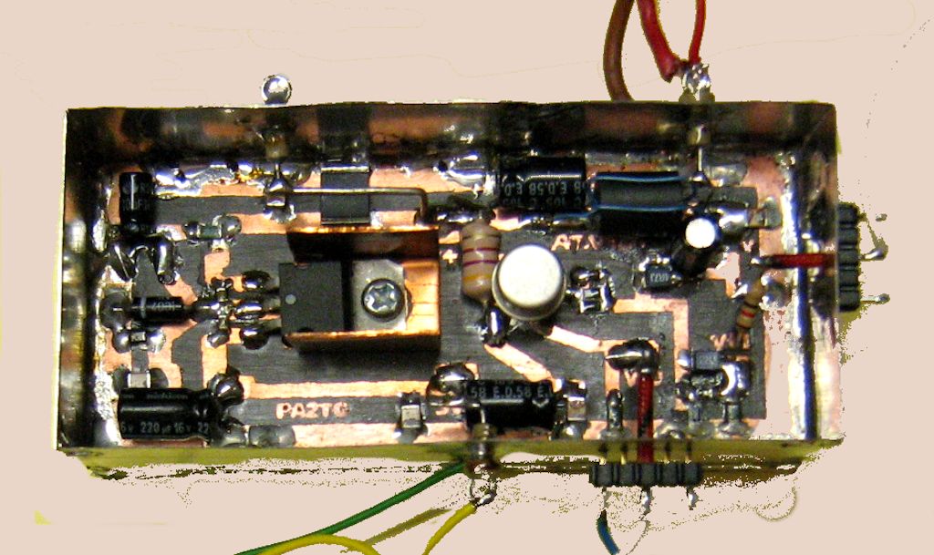
A significant amount of both design and construction work has also been for the next microwave band for ATV, 5.7GHz / 6cms.
Basically I have chosen to use the same principles as in my 10GHz set-ups although various intermediate and generation
frequencies are different. There is a 950MHz uplink controlled in the shack by a local PLL, with the intermediate 1.4GHz fed
as a return and also multiplied to obtain the final 5.650 - 5.850 GHz needed. A couple of these modules can be seen below,
on test and measurement in the workshop:-
The generation multiplier unit:-
And the driver amplifier :-
Both of these on test :-
Yet again (as in the 10GHz units) there is extensive use of SMD components, necessary at this frequency. I have yet to
make a final decision regarding the TX/RX antenna choice for 6cms, a I really have very limited space in my mast installation
as it is now made, with the many antennas involved. I also have to take care of wind considerations.
NOTE - Very recent tests and experience relaying ATV video transmissions
to a repeater (PI6ATV) continue to highlight a probable interference source near that repeater when
using 434.25MHz / 70cms, as serious degradation and intermittent reception
occurs which is observable by receiving it's relayed output on 10.475GHz. This
phenomenen has also been experienced by others, including Anjo, PA0ZR, an amateur friend reasonably
local to my station.
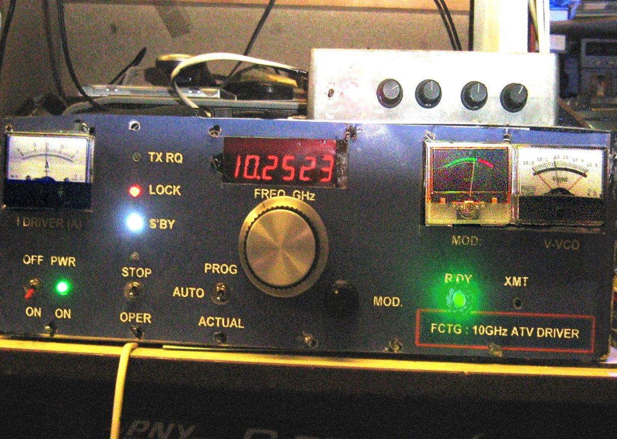
Flirt, hopefully the final version of the 10 GHz ATV set-up has been established - it follows
the same principles at the outset as the previous version but with some marked improvements
in the distribution and isolation of signals and with an easier user interface included,
the telemetry feature (which conveys mast-head operation conditions information) has been
expanded which also gives more checking/diagnostic information when this is required.
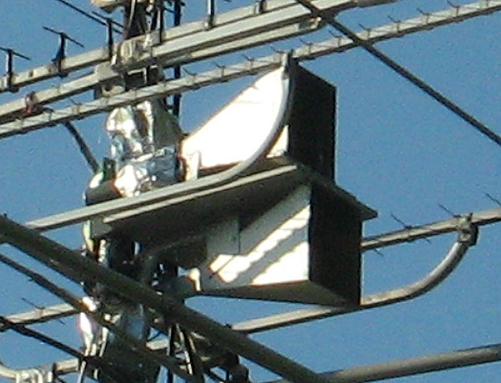
First for this work was the new horn arrangement, there are 2 gain horns for TX and RX for
the main 10 GHz setups, and a further gain-horn (not here) for the monitoring receiver with
it's own LNB and also a separate rotator so that it can be 'aimed' in a direction which
differs from the main antenna array direction. Very near to those horns, mounted in the mast unit
which is a totally weatherproof enclosure, is the remote 'end' of the 10GHz transmitter, with
this unit containing (from left to right): [a] the
5GHz / 640MHz generator / amplifiers, [b] the control / distribution board, [c] the 5GHz -> 10GHz
doubler and ampifier unit, [d] the 10GHz power amplifier and [e] above the P.A., the Telemetry
collection and encoder unit. Spectrum analyser displays show typical 5GHz generator outputs
and (from a second spectrum analyser) the 640MHz divided output which gets sent back down to
the operating equipment indoors for use by the PLL units:-
.
A very brief idea of those
units can be seen below:-
[1] The 5GHz / 640MHz generator and dividers
[2] The control / distribution units' board
[3] And the 10GHz multiplier / amplifier
Indoors, inside the driver control unit, there are also some
newly-developed version of some of the electronics, so here I show just a few of those
boards:-
[1] The "2nd. VVCO" which handles final frequency control of the masthead R.F. units
[2] The programmable local VCO reference for overall frequency control, small but vital
[3] Driver control and protection board which sends back to the masthead unit for overall
control
[4] Lastly the Telemetry decoding, demultiplexing and compensation board, this provides values
for main temperaure, driver temperature, P.A. temperature, all relayed supply levels, a VVCO
return voltage to check operation, R.F. drive level, and power amplifier output level.
NEXT follows an updated current view of the various ATV set-ups which
I have designed and built to date and which are now set in use. There have been a few
modifications and improvements around the place (as should and does happen in any workshop
or lab environment) so just a quick view of some:-
[A] A new startup testcard option, actually originally designed during my last stay in Switzerland,
as is here:
Then the 4 main ATV transmission setups, note there have also been some updates here, internally,
but this is still detectable from the frontpanel fascias which still need renewing(!)
[B] The main 434.25MHz / 70cms transmitter set-up
[C] The main 1.25GHz / 23cms transmitter set-up
[D] The main 2.33GHz / 13cms transmitter set-up
[E] And the new 10GHz / 3cms transmitter set-up
A relayed, recent, 10GHz transmission as seen is also shown below:-
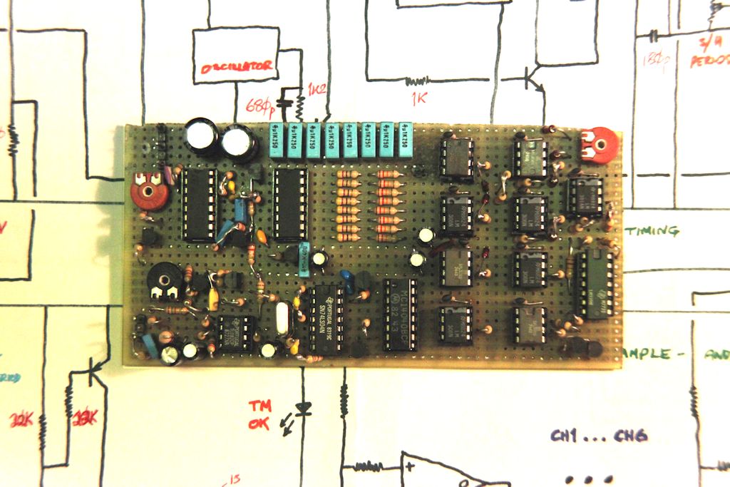
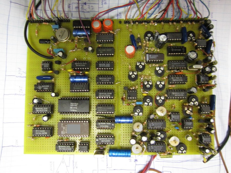
Also from my workshop a year(!) earlier: the finalized version (version 4) of my video processor
is completed. It is far more
stable and at the same time flexible (if you know what you're doing and choose to use
one or more of the 'manual' controls rather than the in-built automatic ones).
Here's an idea of the basic board layout:-
Next, an excellent illustration of the usage of the English language sent to
me by an observant girl whilst in Scotland; read, inwardly digest and subsequently
understand! Click on the image below for this - and a little more!!!!!!
A NEW A.T.V. introduction / test video is now available, and since there are
so many different video decoding and playing software options available for
one's computer nowadays, I have elected to make it available via the YouTube
resource facility which is far more universal and more widely acceptable.
There is now a section in the PA2TG set of pages, one devoted to occasional
device data and datasheets, and this can be accessed from the main PA2TG intro page
- the one you came here from.
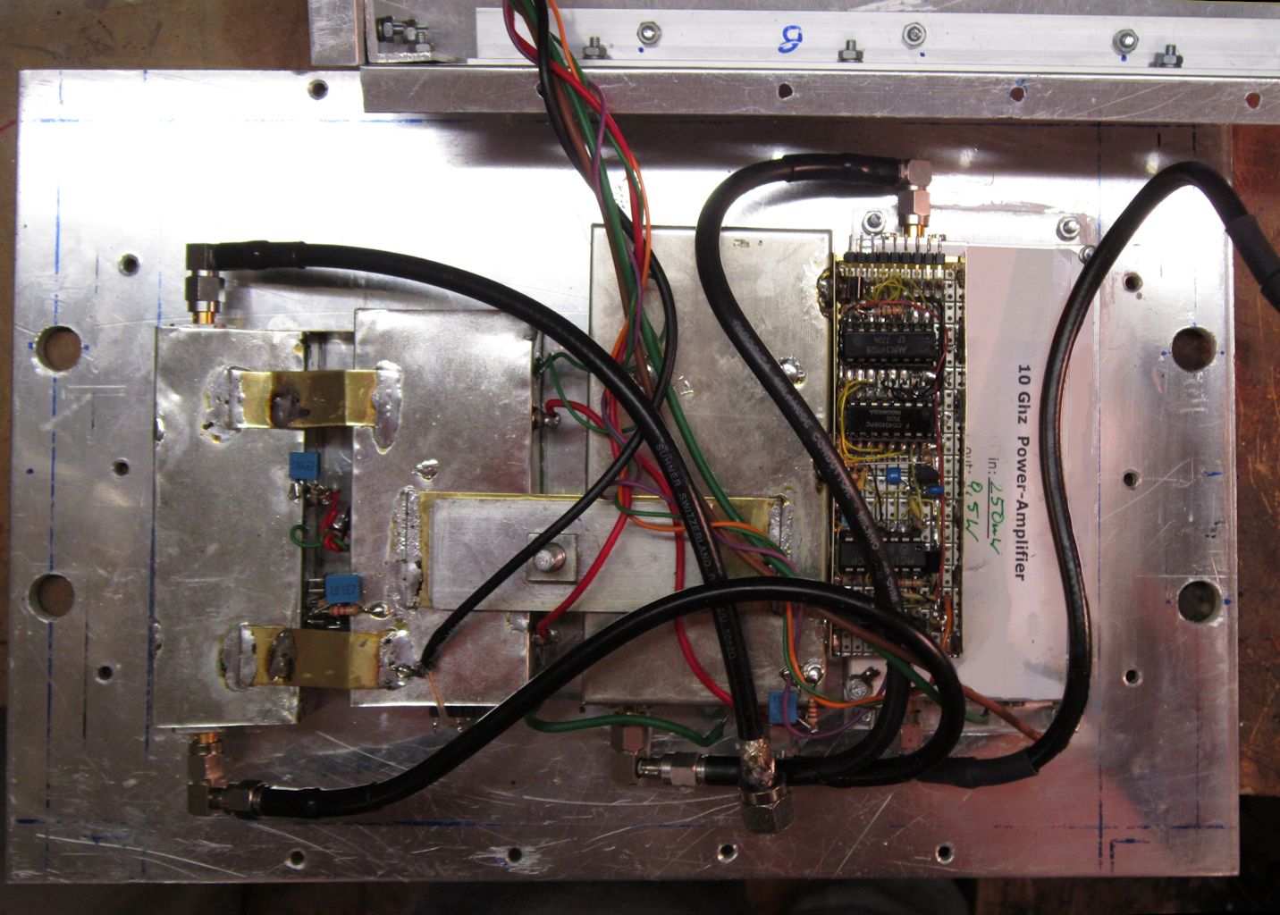
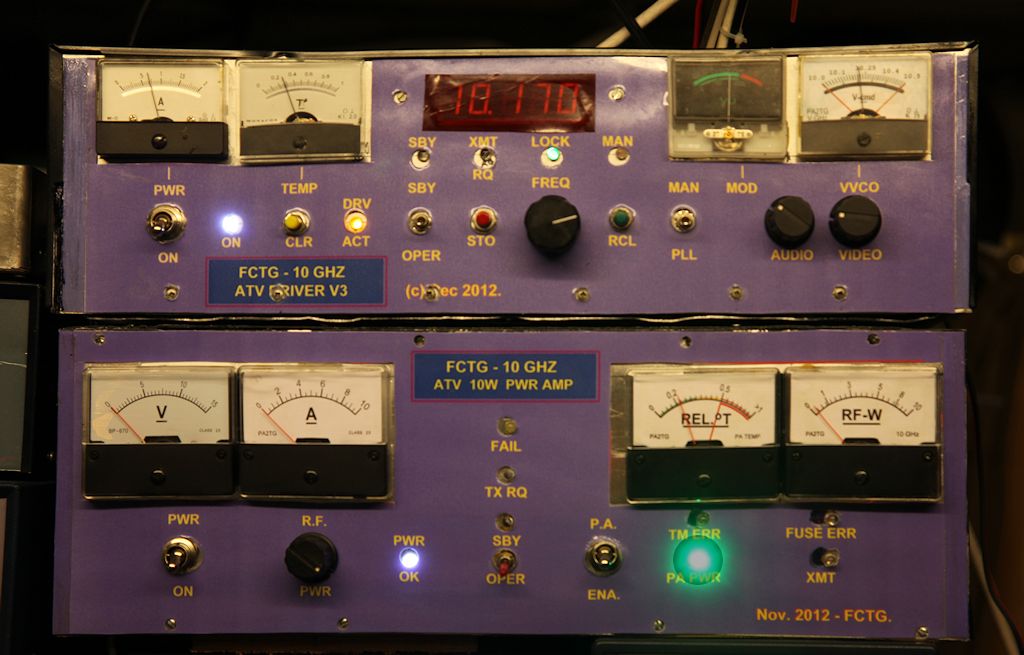
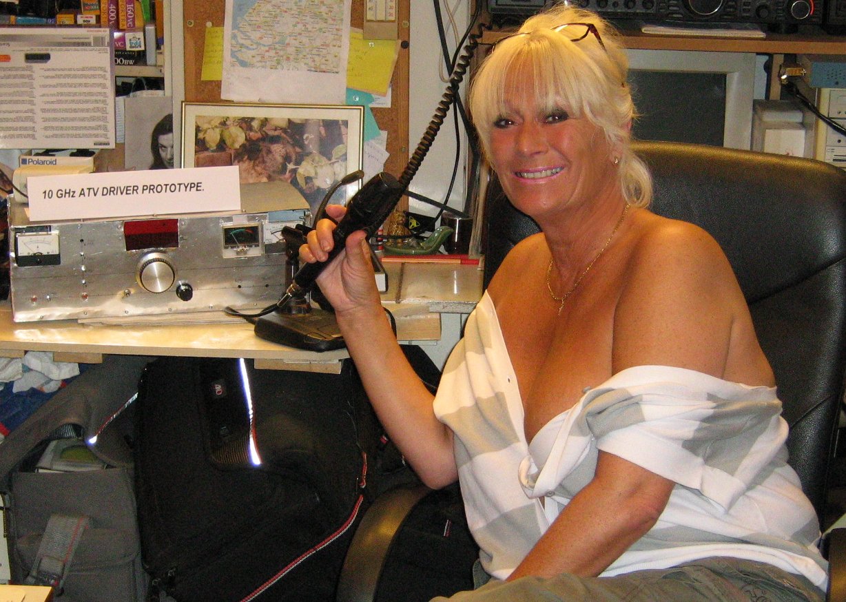
Now next, the original 10 GHz ATV (Amateur TeleVision) transmitter driver and P.A.
have been finally installed, and the driver itself has been partially upgraded.
The original driver prototype modelled by my good theatre/photo friend can be seen below on
the left and the somewhat revised version of that in actual use can be seen
aside below on the right (enlarge by moving over).
This has proved itself as a working basis for a further update (now done) for the design
of a newer 3-cm ATV driver based upon the same principles and approach but
with a more compartmentalised interior structure providing better screening and
less interaction between modules than is presently the case (see earlier above).
Without going into fine detail, the fundamental operation of the 10 GHz ATV
transmitter here is of a kind of 'split VCO plus PLL' that is effectively
shared between the electronics unit on the antenna mast and the associated
electronics at the 'shack' or indoors end. This is realised by the use of microwave
R.F. circuitry and amplification at the antenna end which issues the transmitter
signal the divided-down reference frequency which is sent down to the indoors
unit. This, in its turn, detects this divided reference and counts it, comparing
it to the desired operating frequency and generating an appropriate voltage to
set this frequency such there is no difference, i.e. the transmit frequency
is then equal to the desired frequency set in the indoors unit. Added to
this is of course the modulation, both video and sound-subcarrier which is
itself frequency-modulated, the result being a composite baseband ready to
be frequency-modulated as appropriate for the 10 GHz transmission.
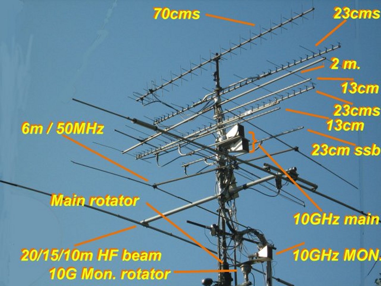
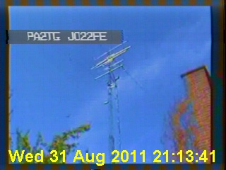
Here is also a new view of the antennae on the main mast here at PA2TG, this
can be seen below: note that there are sometimes several antennae for the one
band/frequency, notably for TX and RX of A.T.V. and sometimes separately for
normal SSB/FM purposes. Here is that stack - remember there are also two
other stacks of antennae that are not located on the main mast (move over to enlarge):-
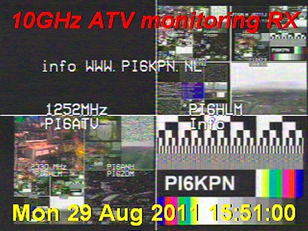
ANOTHER new feature which is now, currently, in the process of being realised
is of a Web-based 'repeat' of my 10 GHz ATV monitoring receiver, this is not
currently in the so-called 'public domain' but restricted to those with
knowledge of the URL and so on because otherwise the bandwidth issues would
potentially become prohibitive. However, an example of how this repeated
ATV monitor image looks like is here below:-
and this image is normally shown much larger,
at 640 x 420 in size. There admittedly
are still a number of bugs in this facility but they will be worked upon as time allows -
remember please, the Web side of things here at PA2TG takes a second or even
lower priority to other activities which occupy significant time here. I share
the thoughts of the great Bob (R.A.) Pease of National Semiconductor,
now unfortunately deceased, in that as a hardware man (not a computer man!)
my favourite programming language is Solder!.
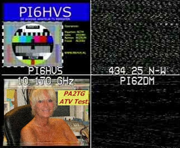
Also, here, a number of pictures of the recent radio/ATV activity that have
been recorded can be seen: they will not be refreshed here like they are in
the links called in the A.T.V. and maybe other sections of this site.
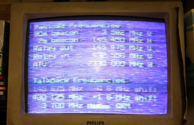
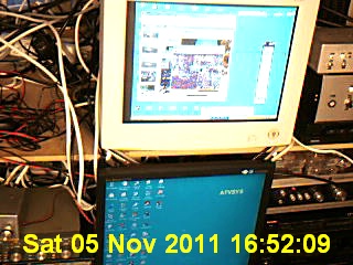
First the ATV status screens.......:-
And the operating area................:-
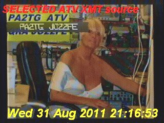
The recent transmit ATV image..:-
And the radio/ATV station used.:-
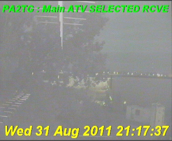
And the selected receive frame.:-
That's all for now - my good 73's and 88's as appropriate, de PA2TG.

I've now also built and finished a reduced version of this processor, for use on the receive side,
to make the most of live ATV received from other stations as well.


You can view it (it is approximately 4 minutes long)
by clicking this link here.
Added to these signals are a subset of other data lines to and from the mast-head electronics
unit such that operation temperature, transmit power level, and reflection
can be monitored from the shack (indoor) units metering.
In accompanient with this is the final P.A. controller and power distributor,
an impression of which can be seen below:-
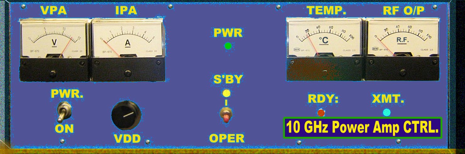
and which as can be seen shows the state of measurements including mast unit
temperature and 10 GHz R.F. power output in addition to the usual voltage and
current metering for the end stages themselves.
Note, as is stated above, this largely covers the previous versions of the 10 GHz
ATV development.
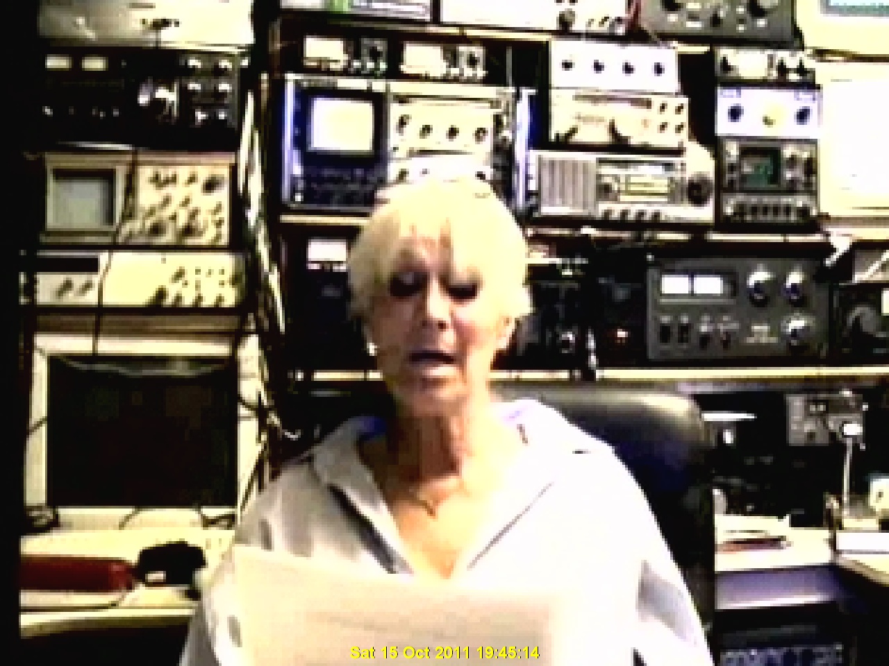
 Then the 'amateur radio' shelf.:-
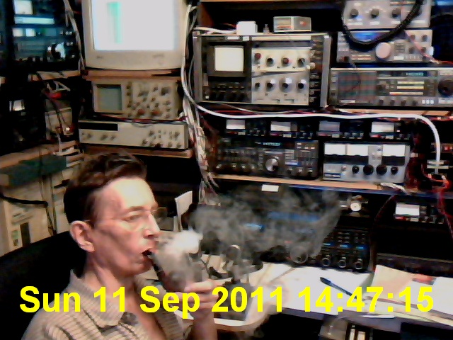
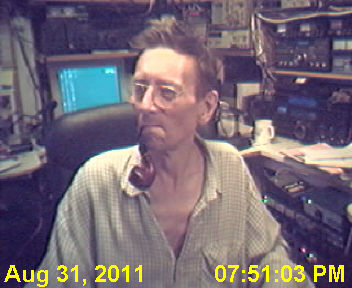
 Here the main operator if there:-
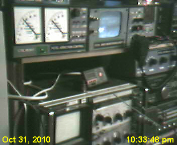
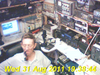
 The radio/T.V. station monitor..:-
 The selected TV transmit frame:-
 You can E-mail the
author of these pages (Trevor Gale) by using
this link, or by sending mail to tgale@tgale.net on the Dutch Internet
service provider XS4ALL.
You can E-mail the
author of these pages (Trevor Gale) by using
this link, or by sending mail to tgale@tgale.net on the Dutch Internet
service provider XS4ALL. 