PA2TG (Trevor Gale)'s Radio Web Page.
As I've said, welcome to the Radio and ATV pages of my PA2TG (my Dutch callsign) station and activities.MORE shelving and equipment has been added since the last update of these pages, so now the latest views of (4 are now necessary!) the station (as of January 2011) are as can be seen below (mouse to enlarge them):-
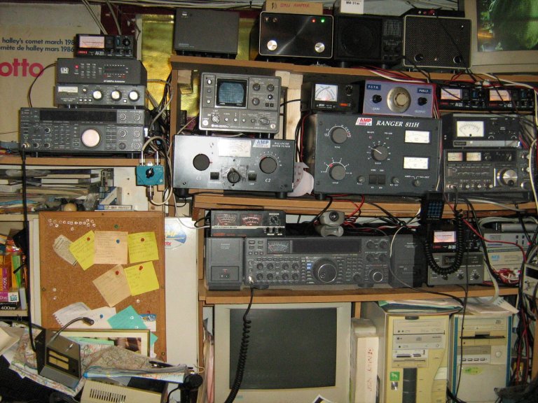
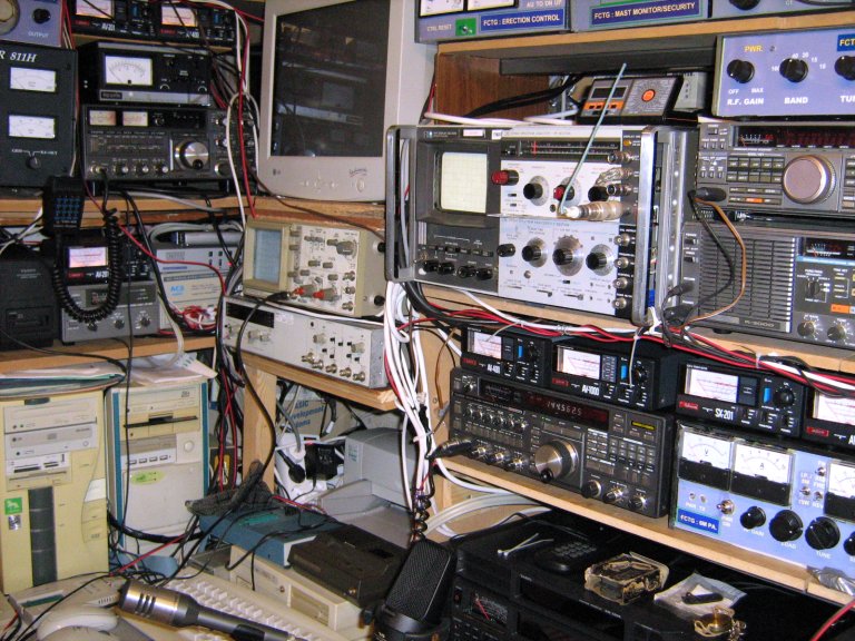
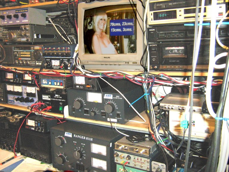
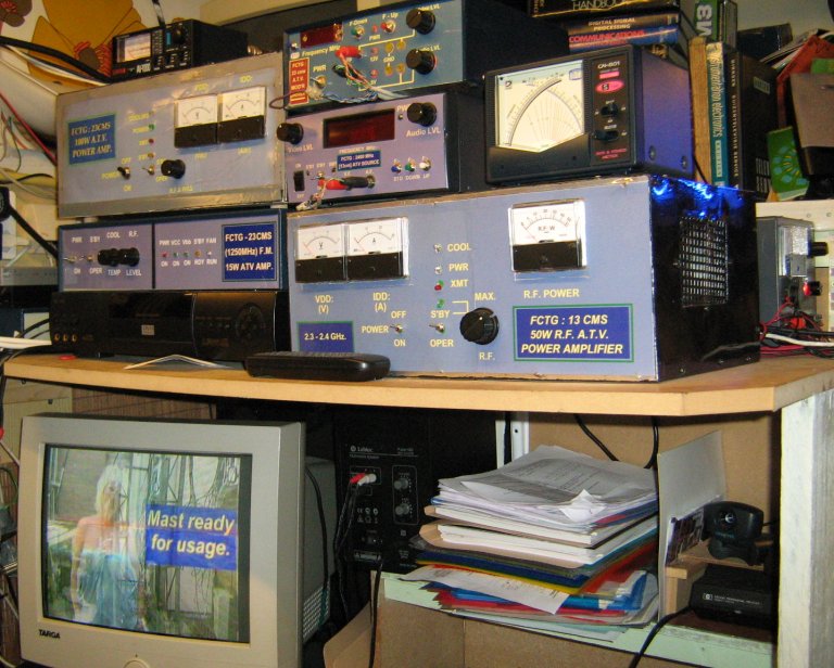
So you see the very left part, the next part,the right half, and the ATV shelf - the only items missing
are the new ATV receiver units.
Power Feed to the equipment is arranged such that a 220V mains
problem, such as a blown fuse or circuit-breaker, does not interfere with the remainder of the house,
meaning that all normal household items such as lighting, washing macine, kitchen equipment,
television etc., etc., are not affected by what may happen in the 'radio shack' or
my workshop and so on. I think that this arrangement is useful and
advantageous for any Radio Amateur, especially if involved in home design and construction
as I am - it's not only sensible but also avoids troublesome
encounters with the XYL!!!
Safety in the 'shack' must also be addressed such that all dangers
associated with the use and maintenance of radio equipment are minimized, so such things as
appropriate fuses and dividing of the feed to the areas used are incorporated. Lighting, small
drills, and equipment such as integrated monitor receivers do not require 15 or 16-amp
circuits, so where this is practical (it isn't always so) they should
use an off-loop from the main shack feed.
On the other hand, powerful H.F. rigs together with linear amplifiers and thei heavy
in-rush currents at switch-on DO require the proper feed, this includes the use of the correct current-handling cable
for such devices; using simple twin-wire flex for 5 amps is asking for trouble and may be even
a fire hazard.
Grounding.
In conjunction with the above, and also having an important effect upon safety,
the grounding of the equipment in the 'shack' is also important. However, this
is important not only for conventional reasons, but also for
radio-frequency reasons: a long wire to ground, which if properly dimensioned
may prove perfectly satisfactory for safety considerations in
normal situations, will prove to be worthless in the context of
high-frequency radio wavelengths.
Consider the following: a transmitter is used on the 14 MHz band
with a safety ground making use of a 5 metre length of ground wire.
Now, the 14 MHz band corresponds to a wavelength of 20 metres, so
our grounding wire represents a quarter-wavelength at that
frequency: here it may well function as an unintentional
quarter-wave antenna rather than a ground - remember, especially at H.F.
(generally accepted as frequencies below 30 MHz), signals are
conveyed by both the antenna wire (typically) together with the
connected ground so we wish to use a better ground than that!
The solution is not as simple as simply connecting a shorter,
more efficient ground to the equipment - indeed this could be dangerous -
since there may well be a slight voltage difference between the house safety ground
but which could give rise to high currents between the two
grounds. What has to be addressed is the possible use of a totally separate ground
circuit for the 'radio shack', or the safe modification of the existing ground
arrangements. This requirement will be different for each individual radio amateur,
as his or her circumstances differ, so I will not delve further into this
subject here - I just wanted to make readers aware of this aspect.
Here at PA2TG, the grounding is taken care of in this respect by
utilising the main ground for the entire property, a separate ground
being safely designed for radio frequencies only being used in the shack
where this is required which itself makes use of it's own
buried grounded metal structure.
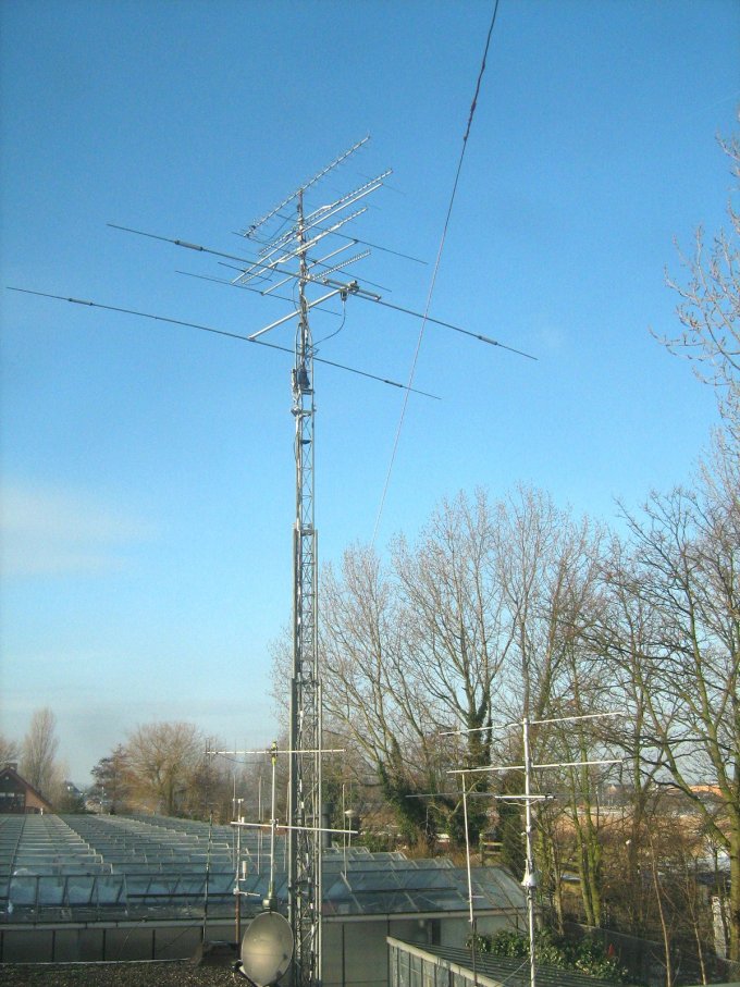
Antennas in use here at PA2TG are many and varied: some of those employed e.g. for VHF / UHF / microwave are mounted on a mast. The erection of this mast was quite a job in itself: some details of the antennas in use as well as the erection of this mast are below:
The antennas all-in-all at PA2TG include the following:-
[a] Two H.F. trapped dipoles (my design again) for 80 - 10m and for 160 - 10m;
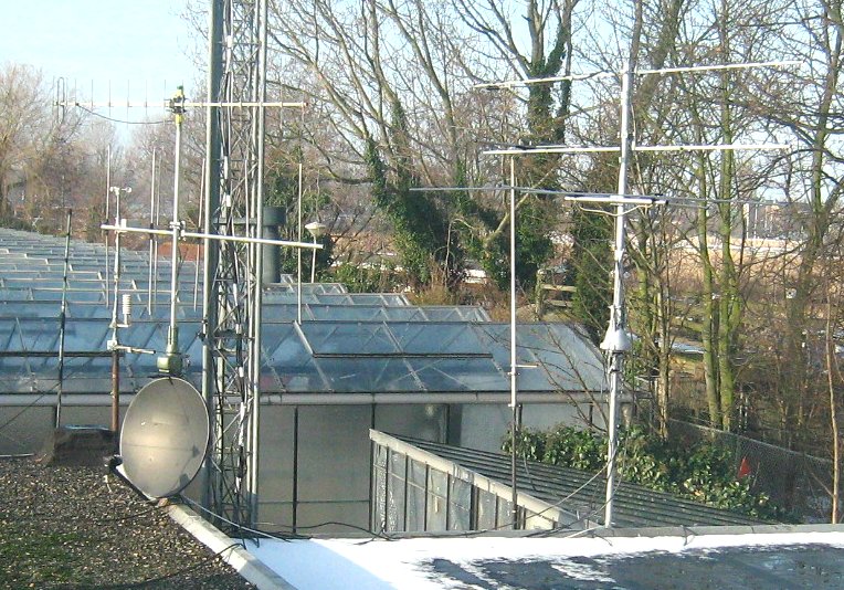
[b] A 2m. 5-element vertical Yagi, and a 70cm. vertical Yagi, on a small rotatable stack, for
use by the sets in the workshop;
[c] A 2m. 7-element horizontal Yagi, a 70cm. horizontal Yagi and a 6m / 50MHz
horizontal 3-element Yagi for use by the backup facilities in the radio
shack;
[d] Omnidirectional radiators similar to the "slim Jim" for 2m and 70cm for use
by the rigs in the computer area;
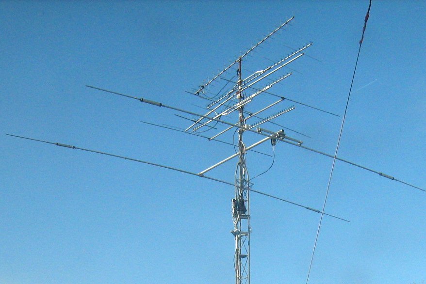
[e] The main, erectable and rotatable, mast antennas for the main radio
station activities as follows:-
*** A 10m / 15m / 20m H.F. Beam antenna for H.F. DX;
*** A 6-metre 3-element horizontal beam;
*** One 11-element horizontal 2m. Yagi;
*** A crossed-Yagi horizontal and vertical Yagi beam for 70cm
(horizontal for ATV, vertical for voice QSO's);
*** Two horizontal 23-cm Yagi beam antennas, for voice QSO's and the
other for 23cm ATV;
*** Another horizontally polarised 23-cm Yagi beam for ATV transmit;
*** A horizontal 13-cms / 2320MHz box-horn-fed Yagi beam primarily for ATV.
*** A second 13-cms / 2320MHz Yagi beam also primarily for ATV.
*** The last antenna is the 3cm / 10GHz main (larger)
horn - that uses the last of the space on the main rotatable support!
*** Additionally now a 3cm / 10GHz gain horn which is mounted at the
side of this main mast on its own rotator, still erected as the rest of the
antennas. Using this, it is possible to rotate the main ATV antennas in transmit
and monitor the signal received by other people or ATV repeaters without moving
the 10GHz horn at all.
Some of these antennas can be seen below (mouse over for bigger shots):-
The 10GHz gain horn plus special LNB can be seen as follows:-
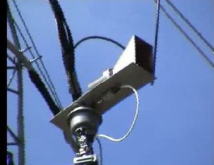
The main RX and TX 10 GHz horn assembly is not yet included in this
series of pictures.
Because I get quite a lot of wind here, I turn and point
in the best direction so as to offer the least resistance for this,
and I also ensure that all is lowered when I go to bed or otherwise
cease use of these antennas. More about the mast itself follows below.
In addition to the antennas there is the terrain camera and a top-level
L.E.D. illumination spotlight to allow viewing the top of the erection
when it is dark outside; it takes 80 seconds to get it up and likewise it
takes 80 seconds to get it down again after use whilst erected. Given the sheer
number of antennas I am very careful again in choosing a time when I have very little
wind to fully erect the mast, and I have a separate out-door weather station
for monitoring this.
The actual erection of this antenna mast (which replaced the oddball collection
of high-mounted antennas that existed before)
and the progress of that can be seen under this link
and in addition some extra work on the antennas and the mast has been
completed since that description was written. Cameras monitor the mast so that
the erection can easily be seen and the view from the top is also available;
at night there is now illumination to assist in this monitoring so that everything
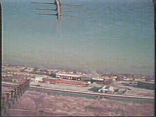
can be seen. The terrain view from the antenna mast can be seen below:
 .
.
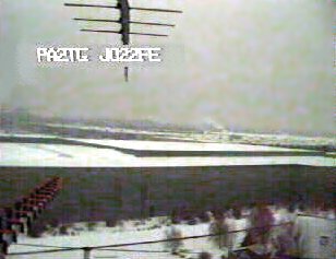
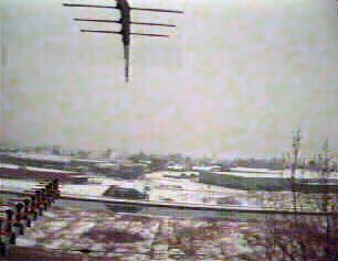
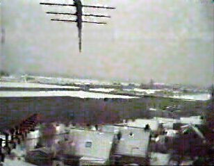
It was winter with snow when working directly after the
erection! On a day with hardly any wind here, I erected the
mast to some 75% and recorded the views over the snow and the rooftops and
the following 3 captures (please remember this camera is for monitoring purposes
only, not to take wonderful photographs!) show what was to be seen from the
mast position and direction:-
As any of you who know me will attest, I am an extremely lazy person
indeed, so much so that I put a great deal of effort into the ease with which
I can be so lazy!
It is with this thought in mind that I developed the mast erection controller,
which allows me to control the erection height of the antenna mast without my
having to keep pressing in a button and holding it down to move the mast in
elevation, and to operate switches to provide illumination of the progress
when it is dark, for observation using one of the monitoring cameras. The unit
allows me to 'dial in' a desired erection height, momentarily press a switch,
and watch the rest on the display. Two meters provide (a) readout of the current
mast height (derived from motor pulse signal feedback and direction), and
given that it takes around 80 seconds this provides some 4000 50-Hz pulses, so
an up/down counter with sufficient bits for 4096 is employed, the most
significant 8 bits of which feed a DAC giving 256 levels of resolution, and (b) the desired 'target'
height desired when this option is used.
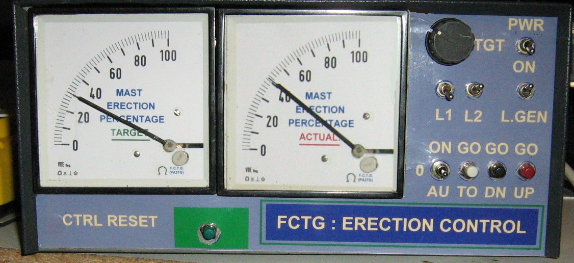
It is also possible to choose to go up or to go down until either a limit sensor switch is tripped or the front-panel 'reset' button is pressed to stop the movement. Either 'on', 'off', or 'au'tomatic control of illumination may be selected, and any of the 3 different light sources can be used / selected for this (L1, L2 and L.GEN). The control reset button halts any erection movement and in auto mode kills any illumination. Conventional logic and discrete circuitry is used in this unit version, it being a prototype; a final version will apear the same but use programmable u-controller chips and memory. The exact place in the station to locate this controller is somewhat difficult as it would appear that I am running out of convenient space, which is important for a lazy person.
It is an unfortunate fact that in todays society there are an increasing number of
people who either due to boredom, drunkenness, delinquency, or the class of
their up-bringing (or lack thereof) have nothing better to do with their time
than to damage or destroy other peoples property. Such people, often young,
are similar to those who take a sharp knife or key and scratch it along your
beautiful cars' paint-job, or wreck your garden furniture, or urinate and defecate
in your front garden. Now, if you wish to persue your hobby of Amateur Radio,
you will most likely make your presence known as you will probably have antenna
wires, or antennas themselves, or perhaps your 'radio shack' is located in a
separate building or large shed away from your main house connected with
mains cable for electrical supply. Any such indications serve to make you a
'target' of interest for the above sort of people, and it is prudent to take
all (legal) precautions to avoid damage or loss of your enjoyment. Such
precautions should include at least some form of alarm to prevent intrusion or
theft, and also to provide an alert in the case of trespass. Prevention is
always better than cure, however, so where either practical or useful it is
wise to take steps to minimize the risk posed by these sorts of people: a
good, sturdy fence taller than a man and difficult to climb perhaps with
spikes and topped off with barbed wire is a good start to the prevention of
trespass, and a movement detector (or more than one if needed) to activate
an alarm and/or take photographs and switch on lamps is another good idea.
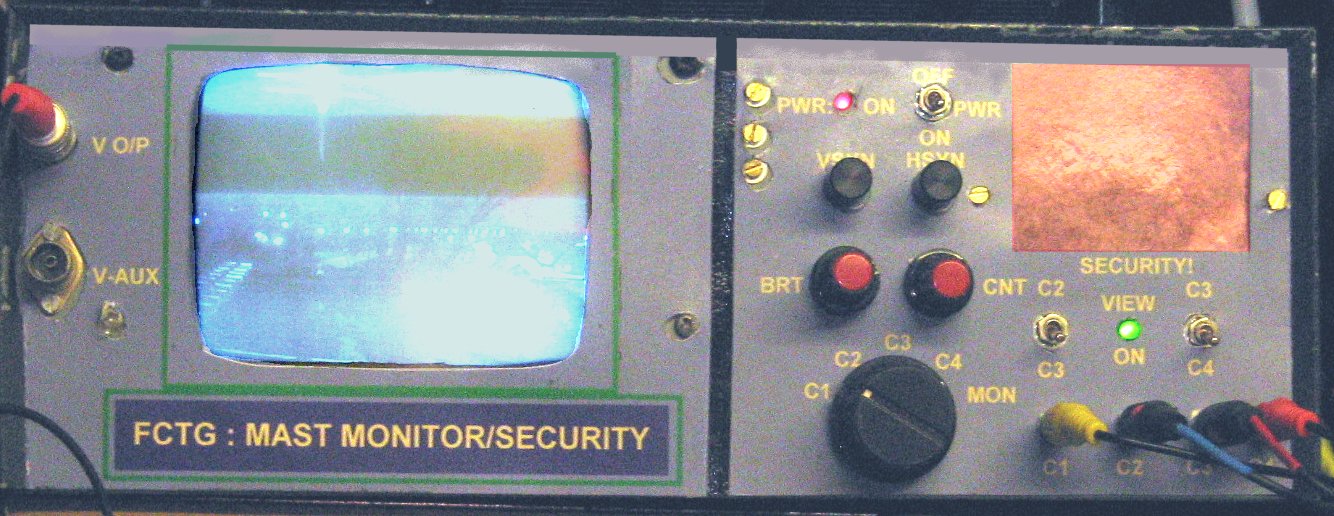
All such measures are made more valuable if you construct a monitor unit, as
I have done (see below):-
that is capable of detecting, recording and timing any unwanted 'events' and
providing a visual as well as text record of their occurrence. Each Radio
Amateur will have differing requirements, different circumstances and different
provisions of working room, aerials, housing and so forth, so it is impossible
to make a general design example that suits everybody - it is merely noteworthy
that this aspect of persuing the hobby be highlighted and most importantly
that Radio Amateurs fully address this aspect of life including the hobby.
This page / these pages will be further updated as I get a round tuit. If
you find any of these round tuits, please send them to me as they are both
rare and expensive to procure: here is a picture of one of them:-
So now you know what they look like, there is
no excuse for delaying things any more!

 You can E-mail the
author of these pages (Trevor Gale) by using
this link, or by sending mail to tgale@tgale.net on the Dutch Internet
service provider XS4ALL.
You can E-mail the
author of these pages (Trevor Gale) by using
this link, or by sending mail to tgale@tgale.net on the Dutch Internet
service provider XS4ALL. 